
Pipe Dimensions:
When discussing pipe dimensions, it’s important to recognize that accurate measurement requires more than just a tape measure. Pipe dimensions are primarily defined by their size and schedule numbers. You may come across terms such as NPS (Nominal Pipe Size), NB (Nominal Bore), and DN (Diameter Nominal). The American Society of Mechanical Engineers (ASME) has established standards, particularly ASME B36.10 and B36.19, which provide guidelines for these dimensions. A complete description of pipe dimensions typically includes the outer diameter (OD), wall thickness (WT), and length of the pipe.
• Nominal Pipe Size (NPS):
The North American standard for pipe sizes is defined by a non-dimensional number known as NPS (Nominal Pipe Size). It’s important to understand that for NPS sizes ranging from 1/8 inch to 12 inches, there is a difference between the NPS value and the actual outside diameter (OD) of the pipe. For example, a pipe with an NPS of 12 inches has an actual OD of 12.75 inches. This discrepancy exists because the NPS values were originally established to ensure a consistent inside diameter. However, for NPS sizes of 14 inches and larger, the NPS value corresponds directly to the actual outside diameter of the pipe.
• Nominal Diameter (DN):
This is the European and international equivalent of NPS, with sizes measured in millimeters. DN denotes the nominal diameter for various pipes and fittings, ensuring they can be interconnected.
• Outer Diameter (OD):
This refers to the actual external measurement of the pipe, which remains consistent for a given NPS size, irrespective of the pipe’s wall thickness.
• Wall Thickness (WT):
The pipe schedule (Sch.) is an important factor in determining pipe dimensions. As the schedule number increases, the wall thickness also increases, which consequently reduces the inside diameter (ID) of the pipe. Thicker walls enhance the pipe’s strength and its ability to withstand internal pressures. Commonly used schedules include SCH 40 and SCH 80, which are popular in various industries because they can handle typical pressure levels. Pipe manufacturers are permitted a fabrication mill tolerance of 12.5% for wall thickness. Piping professionals may specify pipe dimensions in several formats, such as “pipe outside diameter × wall thickness” (for example, Φ 88.9 mm x 5.49 mm) or simply as “NPS x Schedule” (for example, NPS 3 inch x Sch 40).

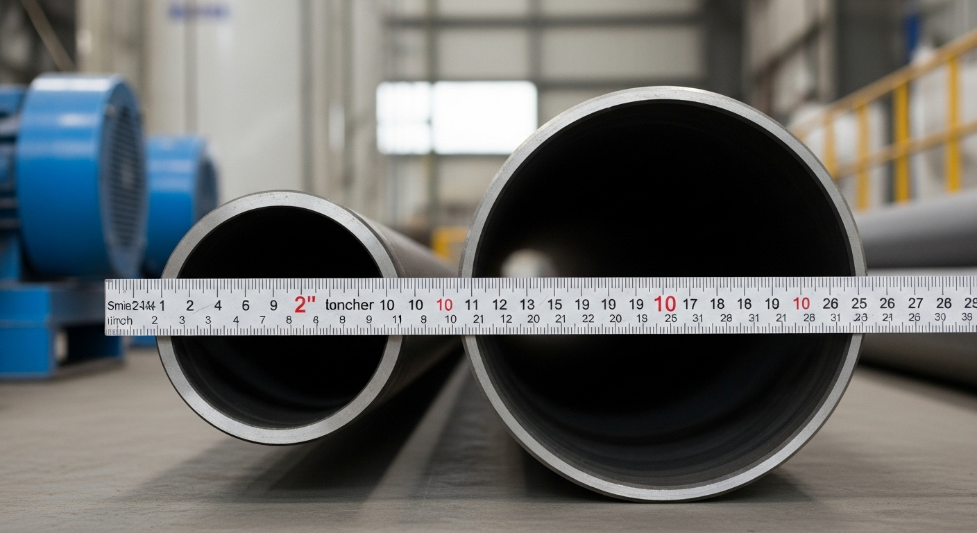
Small-Bore vs. Large-Bore Pipes:
Pipes are also categorized by their bore size:
• Small-bore pipes are generally defined as those with a nominal size of 2 inches or less. These pipes are typically used for applications such as instrument connections, drain lines, sampling points, and vents. While they are often considered non-critical and usually do not require detailed stress analysis, it is important to note that smaller pipes can be susceptible to vibration and potential fatigue failure if not adequately supported.
• Large-bore pipes are those with a nominal size greater than 2 inches.

Pipe Lengths:
Pipes aren’t always manufactured in a single, fixed length. To accommodate varying construction needs, standard pipe lengths are categorized as:
• Single Random Length (SRL): These pipes typically range from 18 to 25 feet (approximately 4.8 to 6.7 meters).
• Double Random Length (DRL): These are longer, usually measuring 38 to 40 feet (approximately 10.7 to 12 meters), with a minimum average length of 10.7 meters.

Pipe End Types:
The preparation of a pipe’s end is crucial for proper connection to other components, significantly affecting the assembly process and the integrity of the joint. Here are the most common types of pipe ends:
• Plain Ends (PE):
The simplest type of pipe end is created by cutting the pipe at a 90-degree angle, perpendicular to its length. Plain end pipes are typically used for smaller sizes (less than 2 inches) and are connected using mechanical couplings, socket weld fittings, or slip-on flanges, which require fillet welding. While these methods offer easier alignment and avoid weld metal intrusion, plain ends may trap liquid and are not recommended in situations where severe erosion or crevice corrosion could occur.

• Beveled Ends (BW):
Often called ‘weld end’ or ‘butt weld end,’ these pipes are cut at an angle, typically a 37.5-degree bevel, to be welded. Beveled ends allow for a strong, reliable leak-proof butt weld, especially practical for larger diameter piping. However, weld intrusion can affect flow, and proper end preparation is necessary.

• Threaded Ends (TE):

• Grooved Mechanical Joints (Grooved Ends):
These pipes have a formed or machined groove at the end that accommodates a gasket. A housing is then tightened around the gasket to secure the connection and create a seal. This design makes disassembly easier and decreases the risk of damaging the piping components.
• Socket & Spigot Ends:
These ends are primarily found in ductile iron and non-metallic pipelines, such as PVC. They can be easily fabricated on-site and can accommodate joints with misalignment of up to 10 degrees. However, they are designed for low-pressure applications and require a special configuration at the ends of the pipes.

• Flanged Ends:
These pipes are designed for situations where a bolted connection is required. They are convenient for on-site assembly and can be used in circumstances where welding is not possible due to material properties or fire hazards. Additionally, they allow for easy dismantling. However, a disadvantage of these pipes is their potential for leakage, and they may not be suitable for piping that experiences high bending moments.
• Buttress Ends:
In glass piping, the ends are connected by bolting with backing flanges. However, this type of connection is not suitable for high-pressure applications. It is essential to understand the various types of pipe ends to ensure proper connections and maintain the overall integrity of any piping system.
Every element of a piping system, from the initial design and specifications to the careful selection of materials, dimensions, and end preparations, is meticulously planned to ensure safe, efficient, and reliable fluid transport. This attention to detail reflects the precision of engineering that, while often overlooked, is essential to our modern world.