
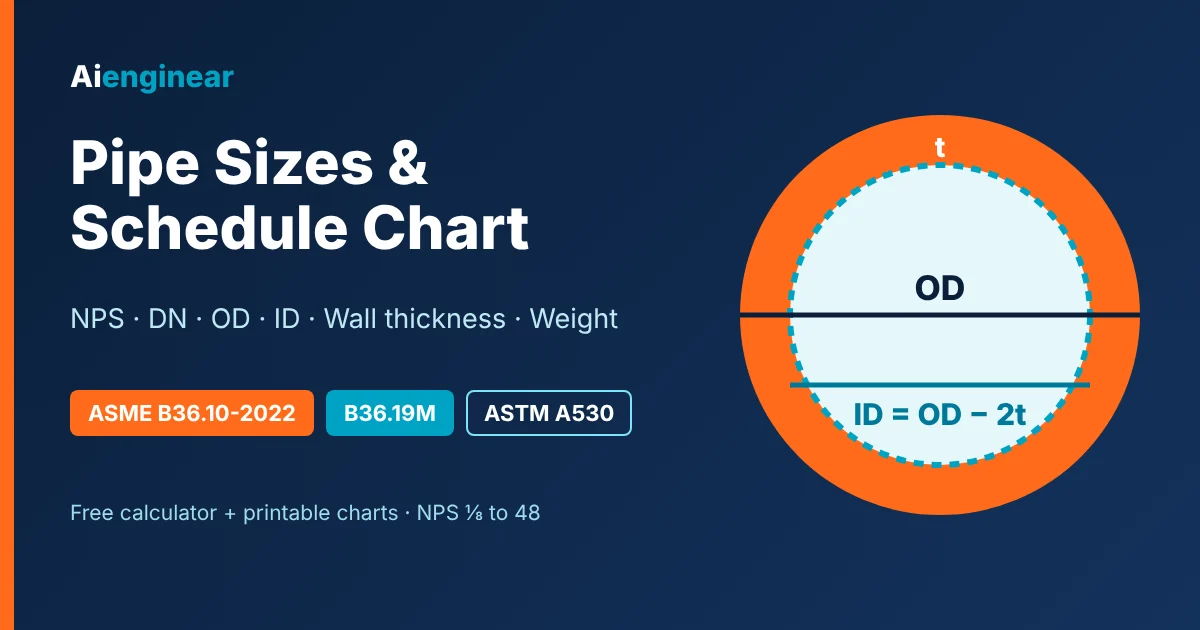
Pipe size is stated as a nominal size – NPS (inches) or DN (metric) – plus a wall designation such as Sch 40, Sch 80 or 40S. The nominal size fixes the outside diameter (OD); the schedule fixes the wall thickness. The bore is therefore ID = OD − 2 × wall. Example: NPS 2 Sch 40 = 2.375 in OD, 0.154 in wall, 2.067 in ID (60.3 / 3.91 / 52.5 mm). The complete pipe schedule chart, NPS to DN table and calculator are below.
Standards used in this guide (reviewed October 2026)
- ASME B36.10-2022 – Welded and Seamless Wrought Steel Pipe (dimensions, schedules, STD/XS/XXS, mass formula).
- ASME B36.19M-2018 – Stainless Steel Pipe (5S, 10S, 40S, 80S).
- ASTM A530/A530M – General requirements for specialized carbon and alloy steel pipe (dimensional tolerances).
- ISO 6708 – Definition of DN; EN 10220 / ISO 4200 – European OD series (for comparison).
- ASME B31.3 / B31.1 – Process and power piping codes that decide the required wall.
What Is Nominal Pipe Size (NPS)?
Nominal Pipe Size (NPS) is the North American size designation for pipe. It is a label, not a measurement: a "6-inch pipe" is NPS 6, whose real outside diameter is 6.625 in and whose bore depends on the wall thickness you choose. The system descends from the old Iron Pipe Size (IPS) practice, where the nominal figure roughly matched the bore of standard-weight pipe.
The key idea for every piping engineer: for a given NPS the OD never changes. Mills hold the OD constant so that fittings, flanges, clamps and supports fit every schedule of that size. When the wall gets thicker, the material grows inward and the ID shrinks.
Why NPS Matches Neither OD nor ID Below NPS 14
From NPS ⅛ to NPS 12 the OD is a fixed historical value that is larger than the nominal number, so the nominal size falls somewhere between the ID and OD. From NPS 14 (DN 350) upward the OD is exactly equal to the NPS in inches. The table below shows both behaviours side by side.
| Pipe | OD (in) | OD (mm) | Wall (in) | Wall (mm) | ID (in) | ID (mm) | Observation |
|---|---|---|---|---|---|---|---|
| NPS 2 Sch 40 | 2.375 | 60.3 | 0.154 | 3.91 | 2.067 | 52.5 | ID ≈ NPS |
| NPS 14 Sch 40 | 14.000 | 355.6 | 0.438 | 11.13 | 13.124 | 333.3 | OD = NPS |
Converting inch dimensions to millimetres
Multiply by 25.4, then round the way ASME B36.10 does: OD of NPS 16 and smaller to the nearest 0.1 mm, larger ODs to the nearest 1 mm, and wall thickness to the nearest 0.01 mm. That is why NPS 18 is listed as 457 mm (not 457.2) and NPS 2 as 60.3 mm.
NPS vs NB vs DN – What Is the Difference?
NB (Nominal Bore) is the British/Asian shop-floor name for the same thing as NPS – "2 inch NB" and "NPS 2" describe the same pipe. DN (Diamètre Nominal) is the dimensionless metric designator defined in ISO 6708. DN is not a millimetre measurement: DN 50 has an OD of 60.3 mm and a Sch 40 bore of 52.5 mm.
A fast rule is DN ≈ NPS × 25, but the exceptions trip people up: NPS 1¼ = DN 32, NPS 1½ = DN 40, NPS 2½ = DN 65, NPS 3½ = DN 90 and NPS 5 = DN 125. Nominal sizes step by ¼ in and ½ in up to NPS 4, then NPS 5 and 6, then by 2 in from NPS 6 to NPS 48, and by 4 in for the larger B36.10 sizes up to NPS 80. Use the filterable chart instead of mental arithmetic.
| NPS (in) | DN | OD (in) | OD (mm) | OD rule |
|---|---|---|---|---|
| ⅛ | 6 | 0.405 | 10.3 | OD fixed, larger than NPS |
| ¼ | 8 | 0.540 | 13.7 | OD fixed, larger than NPS |
| ⅜ | 10 | 0.675 | 17.1 | OD fixed, larger than NPS |
| ½ | 15 | 0.840 | 21.3 | OD fixed, larger than NPS |
| ¾ | 20 | 1.050 | 26.7 | OD fixed, larger than NPS |
| 1 | 25 | 1.315 | 33.4 | OD fixed, larger than NPS |
| 1¼ | 32 | 1.660 | 42.2 | OD fixed, larger than NPS |
| 1½ | 40 | 1.900 | 48.3 | OD fixed, larger than NPS |
| 2 | 50 | 2.375 | 60.3 | OD fixed, larger than NPS |
| 2½ | 65 | 2.875 | 73.0 | OD fixed, larger than NPS |
| 3 | 80 | 3.500 | 88.9 | OD fixed, larger than NPS |
| 3½ | 90 | 4.000 | 101.6 | OD fixed, larger than NPS |
| 4 | 100 | 4.500 | 114.3 | OD fixed, larger than NPS |
| 5 | 125 | 5.563 | 141.3 | OD fixed, larger than NPS |
| 6 | 150 | 6.625 | 168.3 | OD fixed, larger than NPS |
| 8 | 200 | 8.625 | 219.1 | OD fixed, larger than NPS |
| 10 | 250 | 10.750 | 273.0 | OD fixed, larger than NPS |
| 12 | 300 | 12.750 | 323.8 | OD fixed, larger than NPS |
| 14 | 350 | 14.000 | 355.6 | OD = NPS (inch) |
| 16 | 400 | 16.000 | 406.4 | OD = NPS (inch) |
| 18 | 450 | 18.000 | 457.0 | OD = NPS (inch) |
| 20 | 500 | 20.000 | 508.0 | OD = NPS (inch) |
| 22 | 550 | 22.000 | 559.0 | OD = NPS (inch) |
| 24 | 600 | 24.000 | 610.0 | OD = NPS (inch) |
| 26 | 650 | 26.000 | 660.0 | OD = NPS (inch) |
| 28 | 700 | 28.000 | 711.0 | OD = NPS (inch) |
| 30 | 750 | 30.000 | 762.0 | OD = NPS (inch) |
| 32 | 800 | 32.000 | 813.0 | OD = NPS (inch) |
| 34 | 850 | 34.000 | 864.0 | OD = NPS (inch) |
| 36 | 900 | 36.000 | 914.0 | OD = NPS (inch) |
| 38 | 950 | 38.000 | 965.0 | OD = NPS (inch) |
| 40 | 1000 | 40.000 | 1016.0 | OD = NPS (inch) |
| 42 | 1050 | 42.000 | 1067.0 | OD = NPS (inch) |
| 44 | 1100 | 44.000 | 1118.0 | OD = NPS (inch) |
| 46 | 1150 | 46.000 | 1168.0 | OD = NPS (inch) |
| 48 | 1200 | 48.000 | 1219.0 | OD = NPS (inch) |
Same DN, Different OD: ASME vs European Pipe
On international projects you will meet pipe to EN 10220 / ISO 4200. Most ODs match ASME, but a few do not – and a 3 mm OD mismatch means butt-weld fittings, flanges and clamps will not fit. Always state the dimensional standard, not just the DN.
| DN | ASME OD (mm) | EN 10220 OD (mm) | Compatibility |
|---|---|---|---|
| 15 | 21.3 | 21.3 | Same |
| 20 | 26.7 | 26.9 | Minor (≤0.3 mm) – normally interchangeable |
| 25 | 33.4 | 33.7 | Minor (≤0.3 mm) – normally interchangeable |
| 32 | 42.2 | 42.4 | Minor (≤0.3 mm) – normally interchangeable |
| 40 | 48.3 | 48.3 | Same |
| 50 | 60.3 | 60.3 | Same |
| 65 | 73.0 | 76.1 | Different – check fittings & flanges |
| 80 | 88.9 | 88.9 | Same |
| 100 | 114.3 | 114.3 | Same |
| 125 | 141.3 | 139.7 | Different – check fittings & flanges |
| 150 | 168.3 | 168.3 | Same |
| 200 | 219.1 | 219.1 | Same |
| 250 | 273.0 | 273.0 | Same |
| 300 | 323.8 | 323.9 | Minor (≤0.3 mm) – normally interchangeable |
| 350 | 355.6 | 355.6 | Same |
| 400 | 406.4 | 406.4 | Same |
| 450 | 457.0 | 457.0 | Same |
| 500 | 508.0 | 508.0 | Same |
| 600 | 610.0 | 610.0 | Same |
What Is a Pipe Schedule?
A pipe schedule is a standardized designation for wall thickness. Early wrought-iron pipe came in only three weights – Standard (STD), Extra Strong (XS) and Double Extra Strong (XXS). As steam, refinery and petrochemical pressures rose, three steps became too coarse, so the ASA (now ASME) committee introduced schedule numbers from 5 to 160. Their origin is an approximate ratio:
Today that formula is only history. The actual wall for each schedule is a tabulated value in ASME B36.10, and the same schedule number gives a different absolute wall at each size. What stays true is that, for the same NPS, a higher schedule means a thicker wall and a smaller bore. A schedule number is not a pressure rating – that comes from the piping code calculation shown later in this guide.
STD, XS and XXS vs Schedule Numbers
The legacy weight classes are still everywhere on drawings and in ASTM A53/A106 orders. STD equals Sch 40 only up to NPS 10, and XS equals Sch 80 only up to NPS 8. Above those sizes they remain at 0.375 in and 0.500 in respectively, while Sch 40 and Sch 80 keep growing. XXS has no consistent schedule equivalent.
| NPS | DN | STD (Standard) | XS (Extra Strong) | XXS (Double Extra Strong) |
|---|---|---|---|---|
| ⅛ | 6 | 0.068 in / 1.73 mm (= Sch 40) | 0.095 in / 2.41 mm (= Sch 80) | – |
| ¼ | 8 | 0.088 in / 2.24 mm (= Sch 40) | 0.119 in / 3.02 mm (= Sch 80) | – |
| ⅜ | 10 | 0.091 in / 2.31 mm (= Sch 40) | 0.126 in / 3.20 mm (= Sch 80) | – |
| ½ | 15 | 0.109 in / 2.77 mm (= Sch 40) | 0.147 in / 3.73 mm (= Sch 80) | 0.294 in / 7.47 mm |
| ¾ | 20 | 0.113 in / 2.87 mm (= Sch 40) | 0.154 in / 3.91 mm (= Sch 80) | 0.308 in / 7.82 mm |
| 1 | 25 | 0.133 in / 3.38 mm (= Sch 40) | 0.179 in / 4.55 mm (= Sch 80) | 0.358 in / 9.09 mm |
| 1¼ | 32 | 0.140 in / 3.56 mm (= Sch 40) | 0.191 in / 4.85 mm (= Sch 80) | 0.382 in / 9.70 mm |
| 1½ | 40 | 0.145 in / 3.68 mm (= Sch 40) | 0.200 in / 5.08 mm (= Sch 80) | 0.400 in / 10.15 mm |
| 2 | 50 | 0.154 in / 3.91 mm (= Sch 40) | 0.218 in / 5.54 mm (= Sch 80) | 0.436 in / 11.07 mm |
| 2½ | 65 | 0.203 in / 5.16 mm (= Sch 40) | 0.276 in / 7.01 mm (= Sch 80) | 0.552 in / 14.02 mm |
| 3 | 80 | 0.216 in / 5.49 mm (= Sch 40) | 0.300 in / 7.62 mm (= Sch 80) | 0.600 in / 15.24 mm |
| 3½ | 90 | 0.226 in / 5.74 mm (= Sch 40) | 0.318 in / 8.08 mm (= Sch 80) | 0.636 in / 16.15 mm |
| 4 | 100 | 0.237 in / 6.02 mm (= Sch 40) | 0.337 in / 8.56 mm (= Sch 80) | 0.674 in / 17.12 mm |
| 5 | 125 | 0.258 in / 6.55 mm (= Sch 40) | 0.375 in / 9.53 mm (= Sch 80) | 0.750 in / 19.05 mm |
| 6 | 150 | 0.280 in / 7.11 mm (= Sch 40) | 0.432 in / 10.97 mm (= Sch 80) | 0.864 in / 21.95 mm |
| 8 | 200 | 0.322 in / 8.18 mm (= Sch 40) | 0.500 in / 12.70 mm (= Sch 80) | 0.875 in / 22.23 mm |
| 10 | 250 | 0.365 in / 9.27 mm (= Sch 40) | 0.500 in / 12.70 mm (= Sch 60) | 1.000 in / 25.40 mm (= Sch 140) |
| 12 | 300 | 0.375 in / 9.53 mm | 0.500 in / 12.70 mm | 1.000 in / 25.40 mm (= Sch 120) |
| 14 | 350 | 0.375 in / 9.53 mm (= Sch 30) | 0.500 in / 12.70 mm | – |
| 16 | 400 | 0.375 in / 9.53 mm (= Sch 30) | 0.500 in / 12.70 mm (= Sch 40) | – |
| 18 | 450 | 0.375 in / 9.53 mm | 0.500 in / 12.70 mm | – |
| 20 | 500 | 0.375 in / 9.53 mm (= Sch 20) | 0.500 in / 12.70 mm (= Sch 30) | – |
| 22 | 550 | 0.375 in / 9.53 mm (= Sch 20) | 0.500 in / 12.70 mm (= Sch 30) | – |
| 24 | 600 | 0.375 in / 9.53 mm (= Sch 20) | 0.500 in / 12.70 mm | – |
| 26 | 650 | 0.375 in / 9.53 mm | 0.500 in / 12.70 mm (= Sch 20) | – |
| 28 | 700 | 0.375 in / 9.53 mm | 0.500 in / 12.70 mm (= Sch 20) | – |
| 30 | 750 | 0.375 in / 9.53 mm | 0.500 in / 12.70 mm (= Sch 20) | – |
| 32 | 800 | 0.375 in / 9.53 mm | 0.500 in / 12.70 mm (= Sch 20) | – |
| 34 | 850 | 0.375 in / 9.53 mm | 0.500 in / 12.70 mm (= Sch 20) | – |
| 36 | 900 | 0.375 in / 9.53 mm | 0.500 in / 12.70 mm (= Sch 20) | – |
| 38 | 950 | 0.375 in / 9.53 mm | 0.500 in / 12.70 mm | – |
| 40 | 1000 | 0.375 in / 9.53 mm | 0.500 in / 12.70 mm | – |
| 42 | 1050 | 0.375 in / 9.53 mm | 0.500 in / 12.70 mm | – |
| 44 | 1100 | 0.375 in / 9.53 mm | 0.500 in / 12.70 mm | – |
| 46 | 1150 | 0.375 in / 9.53 mm | 0.500 in / 12.70 mm | – |
| 48 | 1200 | 0.375 in / 9.53 mm | 0.500 in / 12.70 mm | – |
ASME B36.10 vs ASME B36.19M (Carbon Steel vs Stainless Steel)
Stainless steel resists corrosion, so it rarely needs a corrosion allowance – and it is expensive. ASME B36.19M therefore defines lighter "S" schedules (5S, 10S, 40S, 80S) that use the same ODs as carbon steel but optimise wall thickness for cost. Carbon and low-alloy steel pipe follows ASME B36.10.
| Item | ASME B36.10 | ASME B36.19M |
|---|---|---|
| Title | Welded and Seamless Wrought Steel Pipe | Stainless Steel Pipe |
| Current edition | ASME B36.10-2022 (supersedes B36.10M-2018) | ASME B36.19M-2018 (check for later edition) |
| Typical materials | Carbon, C-Mn, low-alloy steels (A53, A106, A333, A335, API 5L) | Austenitic, duplex and other stainless steels (A312, A358, A790) |
| Size range | NPS ⅛ to 80 (DN 6–2000) | NPS ⅛ to 30 (DN 6–750) |
| Wall designations | Sch 5*, 10, 20, 30, 40, 60, 80, 100, 120, 140, 160; STD, XS, XXS | Sch 5S, 10S, 40S, 80S |
| Outside diameters | Common OD series | Same OD series as B36.10 |
| Why it exists | Pressure, mechanical strength and corrosion allowance for carbon steel | Thinner, cost-effective walls – stainless needs little or no corrosion allowance |
When Sch 40 Is Not Sch 40S
This is one of the most common requisition errors we see during project material take-offs. Up to NPS 10 the numbers match; from NPS 12 they diverge:
| NPS | DN | ASME B36.10 | ASME B36.19M | S-schedule is |
|---|---|---|---|---|
| 10 | 250 | Sch 80: 0.594 in (15.09 mm) | Sch 80S: 0.500 in (12.70 mm) | 2.39 mm thinner |
| 12 | 300 | Sch 40: 0.406 in (10.31 mm) | Sch 40S: 0.375 in (9.53 mm) | 0.79 mm thinner |
| 12 | 300 | Sch 80: 0.688 in (17.48 mm) | Sch 80S: 0.500 in (12.70 mm) | 4.78 mm thinner |
| 14 | 350 | Sch 10: 0.250 in (6.35 mm) | Sch 10S: 0.188 in (4.78 mm) | 1.57 mm thinner |
| 14 | 350 | Sch 40: 0.438 in (11.13 mm) | Sch 40S: 0.375 in (9.53 mm) | 1.60 mm thinner |
| 14 | 350 | Sch 80: 0.750 in (19.05 mm) | Sch 80S: 0.500 in (12.70 mm) | 6.35 mm thinner |
| 16 | 400 | Sch 10: 0.250 in (6.35 mm) | Sch 10S: 0.188 in (4.78 mm) | 1.57 mm thinner |
| 16 | 400 | Sch 40: 0.500 in (12.70 mm) | Sch 40S: 0.375 in (9.53 mm) | 3.17 mm thinner |
| 16 | 400 | Sch 80: 0.844 in (21.44 mm) | Sch 80S: 0.500 in (12.70 mm) | 8.74 mm thinner |
| 18 | 450 | Sch 10: 0.250 in (6.35 mm) | Sch 10S: 0.188 in (4.78 mm) | 1.57 mm thinner |
| 18 | 450 | Sch 40: 0.562 in (14.27 mm) | Sch 40S: 0.375 in (9.53 mm) | 4.75 mm thinner |
| 18 | 450 | Sch 80: 0.938 in (23.83 mm) | Sch 80S: 0.500 in (12.70 mm) | 11.13 mm thinner |
| 20 | 500 | Sch 10: 0.250 in (6.35 mm) | Sch 10S: 0.218 in (5.54 mm) | 0.81 mm thinner |
| 20 | 500 | Sch 40: 0.594 in (15.09 mm) | Sch 40S: 0.375 in (9.53 mm) | 5.56 mm thinner |
| 20 | 500 | Sch 80: 1.031 in (26.19 mm) | Sch 80S: 0.500 in (12.70 mm) | 13.49 mm thinner |
| 22 | 550 | Sch 10: 0.250 in (6.35 mm) | Sch 10S: 0.218 in (5.54 mm) | 0.81 mm thinner |
| 24 | 600 | Sch 40: 0.688 in (17.48 mm) | Sch 40S: 0.375 in (9.53 mm) | 7.95 mm thinner |
| 24 | 600 | Sch 80: 1.219 in (30.96 mm) | Sch 80S: 0.500 in (12.70 mm) | 18.26 mm thinner |
How to Calculate Pipe ID, Flow Area and Weight
- Find the OD for the NPS/DN from the master chart (e.g. NPS 6 = 6.625 in / 168.3 mm).
- Find the wall thickness for the schedule from the schedule chart (NPS 6 Sch 40 = 0.280 in / 7.11 mm).
- Inside diameter:
ID = OD − 2t= 6.625 − 2 × 0.280 = 6.065 in (154.1 mm). - Flow area:
A = π × ID² / 4= 28.89 in² (186.5 cm²). - Plain-end weight (carbon steel):
W = 10.69 (OD − t) t= 18.99 lb/ft, orW = 0.0246615 (OD − t) t= 28.26 kg/m. - Minimum wall for design checks:
t_min = 0.875 × t= 0.245 in when the purchase spec allows −12.5% mill tolerance.
Pipe Dimension & Weight Calculator (NPS ⅛ to 48)
Pick a standard size and schedule, or enter any OD and wall. The calculator returns ID, flow area, steel weight, water-filled weight, the −12.5% minimum wall and a comparison of every schedule for that size. Switching units converts your custom entries, so the physical pipe stays the same.
Complete Pipe Schedule Chart in Inches
Wall thickness in inches for every ASME schedule from NPS ⅛ to NPS 48. Type a size in the filter box (for example 6 or DN 150), hover to highlight a schedule column, or print a branded A4 copy.
| NPS (in) | OD (in) | 5 | 5S | 10 | 10S | 20 | 30 | 40 | 40S | STD | 60 | 80 | 80S | XS | 100 | 120 | 140 | 160 | XXS |
|---|---|---|---|---|---|---|---|---|---|---|---|---|---|---|---|---|---|---|---|
| ⅛ | 0.405 | – | – | 0.049 | 0.049 | – | 0.057 | 0.068 | 0.068 | 0.068 | – | 0.095 | 0.095 | 0.095 | – | – | – | – | – |
| ¼ | 0.540 | – | – | 0.065 | 0.065 | – | 0.073 | 0.088 | 0.088 | 0.088 | – | 0.119 | 0.119 | 0.119 | – | – | – | – | – |
| ⅜ | 0.675 | – | – | 0.065 | 0.065 | – | 0.073 | 0.091 | 0.091 | 0.091 | – | 0.126 | 0.126 | 0.126 | – | – | – | – | – |
| ½ | 0.840 | 0.065 | 0.065 | 0.083 | 0.083 | – | 0.095 | 0.109 | 0.109 | 0.109 | – | 0.147 | 0.147 | 0.147 | – | – | – | 0.188 | 0.294 |
| ¾ | 1.050 | 0.065 | 0.065 | 0.083 | 0.083 | – | 0.095 | 0.113 | 0.113 | 0.113 | – | 0.154 | 0.154 | 0.154 | – | – | – | 0.219 | 0.308 |
| 1 | 1.315 | 0.065 | 0.065 | 0.109 | 0.109 | – | 0.114 | 0.133 | 0.133 | 0.133 | – | 0.179 | 0.179 | 0.179 | – | – | – | 0.250 | 0.358 |
| 1¼ | 1.660 | 0.065 | 0.065 | 0.109 | 0.109 | – | 0.117 | 0.140 | 0.140 | 0.140 | – | 0.191 | 0.191 | 0.191 | – | – | – | 0.250 | 0.382 |
| 1½ | 1.900 | 0.065 | 0.065 | 0.109 | 0.109 | – | 0.125 | 0.145 | 0.145 | 0.145 | – | 0.200 | 0.200 | 0.200 | – | – | – | 0.281 | 0.400 |
| 2 | 2.375 | 0.065 | 0.065 | 0.109 | 0.109 | – | 0.125 | 0.154 | 0.154 | 0.154 | – | 0.218 | 0.218 | 0.218 | – | – | – | 0.344 | 0.436 |
| 2½ | 2.875 | 0.083 | 0.083 | 0.120 | 0.120 | – | 0.188 | 0.203 | 0.203 | 0.203 | – | 0.276 | 0.276 | 0.276 | – | – | – | 0.375 | 0.552 |
| 3 | 3.500 | 0.083 | 0.083 | 0.120 | 0.120 | – | 0.188 | 0.216 | 0.216 | 0.216 | – | 0.300 | 0.300 | 0.300 | – | – | – | 0.438 | 0.600 |
| 3½ | 4.000 | 0.083 | 0.083 | 0.120 | 0.120 | – | 0.188 | 0.226 | 0.226 | 0.226 | – | 0.318 | 0.318 | 0.318 | – | – | – | – | 0.636 |
| 4 | 4.500 | 0.083 | 0.083 | 0.120 | 0.120 | – | 0.188 | 0.237 | 0.237 | 0.237 | – | 0.337 | 0.337 | 0.337 | – | 0.438 | – | 0.531 | 0.674 |
| 5 | 5.563 | 0.109 | 0.109 | 0.134 | 0.134 | – | – | 0.258 | 0.258 | 0.258 | – | 0.375 | 0.375 | 0.375 | – | 0.500 | – | 0.625 | 0.750 |
| 6 | 6.625 | 0.109 | 0.109 | 0.134 | 0.134 | – | – | 0.280 | 0.280 | 0.280 | – | 0.432 | 0.432 | 0.432 | – | 0.562 | – | 0.719 | 0.864 |
| 8 | 8.625 | 0.109 | 0.109 | 0.148 | 0.148 | 0.250 | 0.277 | 0.322 | 0.322 | 0.322 | 0.406 | 0.500 | 0.500 | 0.500 | 0.594 | 0.719 | 0.812 | 0.906 | 0.875 |
| 10 | 10.750 | 0.134 | 0.134 | 0.165 | 0.165 | 0.250 | 0.307 | 0.365 | 0.365 | 0.365 | 0.500 | 0.594 | 0.500 | 0.500 | 0.719 | 0.844 | 1.000 | 1.125 | 1.000 |
| 12 | 12.750 | 0.156 | 0.156 | 0.180 | 0.180 | 0.250 | 0.330 | 0.406 | 0.375 | 0.375 | 0.562 | 0.688 | 0.500 | 0.500 | 0.844 | 1.000 | 1.125 | 1.312 | 1.000 |
| 14 | 14.000 | 0.156 | 0.156 | 0.250 | 0.188 | 0.312 | 0.375 | 0.438 | 0.375 | 0.375 | 0.594 | 0.750 | 0.500 | 0.500 | 0.938 | 1.094 | 1.250 | 1.406 | – |
| 16 | 16.000 | 0.165 | 0.165 | 0.250 | 0.188 | 0.312 | 0.375 | 0.500 | 0.375 | 0.375 | 0.656 | 0.844 | 0.500 | 0.500 | 1.031 | 1.219 | 1.438 | 1.594 | – |
| 18 | 18.000 | 0.165 | 0.165 | 0.250 | 0.188 | 0.312 | 0.438 | 0.562 | 0.375 | 0.375 | 0.750 | 0.938 | 0.500 | 0.500 | 1.156 | 1.375 | 1.562 | 1.781 | – |
| 20 | 20.000 | 0.188 | 0.188 | 0.250 | 0.218 | 0.375 | 0.500 | 0.594 | 0.375 | 0.375 | 0.812 | 1.031 | 0.500 | 0.500 | 1.281 | 1.500 | 1.750 | 1.969 | – |
| 22 | 22.000 | 0.188 | 0.188 | 0.250 | 0.218 | 0.375 | 0.500 | – | – | 0.375 | 0.875 | 1.125 | – | 0.500 | 1.375 | 1.625 | 1.875 | 2.125 | – |
| 24 | 24.000 | 0.218 | 0.218 | 0.250 | 0.250 | 0.375 | 0.562 | 0.688 | 0.375 | 0.375 | 0.969 | 1.219 | 0.500 | 0.500 | 1.531 | 1.812 | 2.062 | 2.344 | – |
| 26 | 26.000 | – | – | 0.312 | – | 0.500 | – | – | – | 0.375 | – | – | – | 0.500 | – | – | – | – | – |
| 28 | 28.000 | – | – | 0.312 | – | 0.500 | 0.625 | – | – | 0.375 | – | – | – | 0.500 | – | – | – | – | – |
| 30 | 30.000 | 0.250 | 0.250 | 0.312 | 0.312 | 0.500 | 0.625 | – | – | 0.375 | – | – | – | 0.500 | – | – | – | – | – |
| 32 | 32.000 | – | – | 0.312 | – | 0.500 | 0.625 | 0.688 | – | 0.375 | – | – | – | 0.500 | – | – | – | – | – |
| 34 | 34.000 | – | – | 0.312 | – | 0.500 | 0.625 | 0.688 | – | 0.375 | – | – | – | 0.500 | – | – | – | – | – |
| 36 | 36.000 | – | – | 0.312 | – | 0.500 | 0.625 | 0.750 | – | 0.375 | – | – | – | 0.500 | – | – | – | – | – |
| 38 | 38.000 | – | – | – | – | – | – | – | – | 0.375 | – | – | – | 0.500 | – | – | – | – | – |
| 40 | 40.000 | – | – | – | – | – | – | – | – | 0.375 | – | – | – | 0.500 | – | – | – | – | – |
| 42 | 42.000 | – | – | – | – | – | – | – | – | 0.375 | – | – | – | 0.500 | – | – | – | – | – |
| 44 | 44.000 | – | – | – | – | – | – | – | – | 0.375 | – | – | – | 0.500 | – | – | – | – | – |
| 46 | 46.000 | – | – | – | – | – | – | – | – | 0.375 | – | – | – | 0.500 | – | – | – | – | – |
| 48 | 48.000 | – | – | – | – | – | – | – | – | 0.375 | – | – | – | 0.500 | – | – | – | – | – |
Complete Pipe Schedule Chart in Millimetres
The same data in SI units, as published in the standards. Use these values for metric isometrics, MTOs and stress models rather than converting inch values yourself.
| DN | OD (mm) | 5 | 5S | 10 | 10S | 20 | 30 | 40 | 40S | STD | 60 | 80 | 80S | XS | 100 | 120 | 140 | 160 | XXS |
|---|---|---|---|---|---|---|---|---|---|---|---|---|---|---|---|---|---|---|---|
| 6 | 10.3 | – | – | 1.24 | 1.24 | – | 1.45 | 1.73 | 1.73 | 1.73 | – | 2.41 | 2.41 | 2.41 | – | – | – | – | – |
| 8 | 13.7 | – | – | 1.65 | 1.65 | – | 1.85 | 2.24 | 2.24 | 2.24 | – | 3.02 | 3.02 | 3.02 | – | – | – | – | – |
| 10 | 17.1 | – | – | 1.65 | 1.65 | – | 1.85 | 2.31 | 2.31 | 2.31 | – | 3.20 | 3.20 | 3.20 | – | – | – | – | – |
| 15 | 21.3 | 1.65 | 1.65 | 2.11 | 2.11 | – | 2.41 | 2.77 | 2.77 | 2.77 | – | 3.73 | 3.73 | 3.73 | – | – | – | 4.78 | 7.47 |
| 20 | 26.7 | 1.65 | 1.65 | 2.11 | 2.11 | – | 2.41 | 2.87 | 2.87 | 2.87 | – | 3.91 | 3.91 | 3.91 | – | – | – | 5.56 | 7.82 |
| 25 | 33.4 | 1.65 | 1.65 | 2.77 | 2.77 | – | 2.90 | 3.38 | 3.38 | 3.38 | – | 4.55 | 4.55 | 4.55 | – | – | – | 6.35 | 9.09 |
| 32 | 42.2 | 1.65 | 1.65 | 2.77 | 2.77 | – | 2.97 | 3.56 | 3.56 | 3.56 | – | 4.85 | 4.85 | 4.85 | – | – | – | 6.35 | 9.70 |
| 40 | 48.3 | 1.65 | 1.65 | 2.77 | 2.77 | – | 3.18 | 3.68 | 3.68 | 3.68 | – | 5.08 | 5.08 | 5.08 | – | – | – | 7.14 | 10.15 |
| 50 | 60.3 | 1.65 | 1.65 | 2.77 | 2.77 | – | 3.18 | 3.91 | 3.91 | 3.91 | – | 5.54 | 5.54 | 5.54 | – | – | – | 8.74 | 11.07 |
| 65 | 73.0 | 2.11 | 2.11 | 3.05 | 3.05 | – | 4.78 | 5.16 | 5.16 | 5.16 | – | 7.01 | 7.01 | 7.01 | – | – | – | 9.53 | 14.02 |
| 80 | 88.9 | 2.11 | 2.11 | 3.05 | 3.05 | – | 4.78 | 5.49 | 5.49 | 5.49 | – | 7.62 | 7.62 | 7.62 | – | – | – | 11.13 | 15.24 |
| 90 | 101.6 | 2.11 | 2.11 | 3.05 | 3.05 | – | 4.78 | 5.74 | 5.74 | 5.74 | – | 8.08 | 8.08 | 8.08 | – | – | – | – | 16.15 |
| 100 | 114.3 | 2.11 | 2.11 | 3.05 | 3.05 | – | 4.78 | 6.02 | 6.02 | 6.02 | – | 8.56 | 8.56 | 8.56 | – | 11.13 | – | 13.49 | 17.12 |
| 125 | 141.3 | 2.77 | 2.77 | 3.40 | 3.40 | – | – | 6.55 | 6.55 | 6.55 | – | 9.53 | 9.53 | 9.53 | – | 12.70 | – | 15.88 | 19.05 |
| 150 | 168.3 | 2.77 | 2.77 | 3.40 | 3.40 | – | – | 7.11 | 7.11 | 7.11 | – | 10.97 | 10.97 | 10.97 | – | 14.27 | – | 18.26 | 21.95 |
| 200 | 219.1 | 2.77 | 2.77 | 3.76 | 3.76 | 6.35 | 7.04 | 8.18 | 8.18 | 8.18 | 10.31 | 12.70 | 12.70 | 12.70 | 15.09 | 18.26 | 20.62 | 23.01 | 22.23 |
| 250 | 273.0 | 3.40 | 3.40 | 4.19 | 4.19 | 6.35 | 7.80 | 9.27 | 9.27 | 9.27 | 12.70 | 15.09 | 12.70 | 12.70 | 18.26 | 21.44 | 25.40 | 28.58 | 25.40 |
| 300 | 323.8 | 3.96 | 3.96 | 4.57 | 4.57 | 6.35 | 8.38 | 10.31 | 9.53 | 9.53 | 14.27 | 17.48 | 12.70 | 12.70 | 21.44 | 25.40 | 28.58 | 33.32 | 25.40 |
| 350 | 355.6 | 3.96 | 3.96 | 6.35 | 4.78 | 7.92 | 9.53 | 11.13 | 9.53 | 9.53 | 15.09 | 19.05 | 12.70 | 12.70 | 23.83 | 27.79 | 31.75 | 35.71 | – |
| 400 | 406.4 | 4.19 | 4.19 | 6.35 | 4.78 | 7.92 | 9.53 | 12.70 | 9.53 | 9.53 | 16.66 | 21.44 | 12.70 | 12.70 | 26.19 | 30.96 | 36.53 | 40.49 | – |
| 450 | 457.0 | 4.19 | 4.19 | 6.35 | 4.78 | 7.92 | 11.13 | 14.27 | 9.53 | 9.53 | 19.05 | 23.83 | 12.70 | 12.70 | 29.36 | 34.93 | 39.67 | 45.24 | – |
| 500 | 508.0 | 4.78 | 4.78 | 6.35 | 5.54 | 9.53 | 12.70 | 15.09 | 9.53 | 9.53 | 20.62 | 26.19 | 12.70 | 12.70 | 32.54 | 38.10 | 44.45 | 50.01 | – |
| 550 | 559.0 | 4.78 | 4.78 | 6.35 | 5.54 | 9.53 | 12.70 | – | – | 9.53 | 22.23 | 28.58 | – | 12.70 | 34.93 | 41.28 | 47.63 | 53.98 | – |
| 600 | 610.0 | 5.54 | 5.54 | 6.35 | 6.35 | 9.53 | 14.27 | 17.48 | 9.53 | 9.53 | 24.61 | 30.96 | 12.70 | 12.70 | 38.89 | 46.02 | 52.37 | 59.54 | – |
| 650 | 660.0 | – | – | 7.92 | – | 12.70 | – | – | – | 9.53 | – | – | – | 12.70 | – | – | – | – | – |
| 700 | 711.0 | – | – | 7.92 | – | 12.70 | 15.88 | – | – | 9.53 | – | – | – | 12.70 | – | – | – | – | – |
| 750 | 762.0 | 6.35 | 6.35 | 7.92 | 7.92 | 12.70 | 15.88 | – | – | 9.53 | – | – | – | 12.70 | – | – | – | – | – |
| 800 | 813.0 | – | – | 7.92 | – | 12.70 | 15.88 | 17.48 | – | 9.53 | – | – | – | 12.70 | – | – | – | – | – |
| 850 | 864.0 | – | – | 7.92 | – | 12.70 | 15.88 | 17.48 | – | 9.53 | – | – | – | 12.70 | – | – | – | – | – |
| 900 | 914.0 | – | – | 7.92 | – | 12.70 | 15.88 | 19.05 | – | 9.53 | – | – | – | 12.70 | – | – | – | – | – |
| 950 | 965.0 | – | – | – | – | – | – | – | – | 9.53 | – | – | – | 12.70 | – | – | – | – | – |
| 1000 | 1016.0 | – | – | – | – | – | – | – | – | 9.53 | – | – | – | 12.70 | – | – | – | – | – |
| 1050 | 1067.0 | – | – | – | – | – | – | – | – | 9.53 | – | – | – | 12.70 | – | – | – | – | – |
| 1100 | 1118.0 | – | – | – | – | – | – | – | – | 9.53 | – | – | – | 12.70 | – | – | – | – | – |
| 1150 | 1168.0 | – | – | – | – | – | – | – | – | 9.53 | – | – | – | 12.70 | – | – | – | – | – |
| 1200 | 1219.0 | – | – | – | – | – | – | – | – | 9.53 | – | – | – | 12.70 | – | – | – | – | – |
Carbon Steel Pipe Weight Chart
Weight drives support design, lifting plans and freight. Values below are plain-end steel weight only; add contents, insulation and lining separately (the calculator above adds water for hydrotest load checks).
| NPS | DN | Sch 40 | STD | Sch 80 | XS | Sch 160 |
|---|---|---|---|---|---|---|
| ⅛ | 6 | 0.24 / 0.37 | 0.24 / 0.37 | 0.31 / 0.47 | 0.31 / 0.47 | – |
| ¼ | 8 | 0.43 / 0.63 | 0.43 / 0.63 | 0.54 / 0.80 | 0.54 / 0.80 | – |
| ⅜ | 10 | 0.57 / 0.84 | 0.57 / 0.84 | 0.74 / 1.10 | 0.74 / 1.10 | – |
| ½ | 15 | 0.85 / 1.27 | 0.85 / 1.27 | 1.09 / 1.62 | 1.09 / 1.62 | 1.31 / 1.95 |
| ¾ | 20 | 1.13 / 1.69 | 1.13 / 1.69 | 1.48 / 2.20 | 1.48 / 2.20 | 1.95 / 2.90 |
| 1 | 25 | 1.68 / 2.50 | 1.68 / 2.50 | 2.17 / 3.24 | 2.17 / 3.24 | 2.85 / 4.24 |
| 1¼ | 32 | 2.27 / 3.39 | 2.27 / 3.39 | 3.00 / 4.47 | 3.00 / 4.47 | 3.77 / 5.61 |
| 1½ | 40 | 2.72 / 4.05 | 2.72 / 4.05 | 3.63 / 5.41 | 3.63 / 5.41 | 4.86 / 7.25 |
| 2 | 50 | 3.66 / 5.44 | 3.66 / 5.44 | 5.03 / 7.48 | 5.03 / 7.48 | 7.47 / 11.11 |
| 2½ | 65 | 5.80 / 8.63 | 5.80 / 8.63 | 7.67 / 11.41 | 7.67 / 11.41 | 10.02 / 14.92 |
| 3 | 80 | 7.58 / 11.29 | 7.58 / 11.29 | 10.26 / 15.27 | 10.26 / 15.27 | 14.34 / 21.35 |
| 3½ | 90 | 9.12 / 13.57 | 9.12 / 13.57 | 12.52 / 18.64 | 12.52 / 18.64 | – |
| 4 | 100 | 10.80 / 16.08 | 10.80 / 16.08 | 15.00 / 22.32 | 15.00 / 22.32 | 22.53 / 33.54 |
| 5 | 125 | 14.63 / 21.77 | 14.63 / 21.77 | 20.80 / 30.97 | 20.80 / 30.97 | 32.99 / 49.12 |
| 6 | 150 | 18.99 / 28.26 | 18.99 / 28.26 | 28.60 / 42.56 | 28.60 / 42.56 | 45.39 / 67.57 |
| 8 | 200 | 28.58 / 42.55 | 28.58 / 42.55 | 43.43 / 64.64 | 43.43 / 64.64 | 74.76 / 111.27 |
| 10 | 250 | 40.52 / 60.29 | 40.52 / 60.29 | 64.49 / 95.98 | 54.79 / 81.53 | 115.75 / 172.27 |
| 12 | 300 | 53.57 / 79.71 | 49.61 / 73.86 | 88.71 / 132.05 | 65.48 / 97.44 | 160.42 / 238.69 |
| 14 | 350 | 63.50 / 94.55 | 54.62 / 81.33 | 106.23 / 158.11 | 72.16 / 107.40 | 189.29 / 281.72 |
| 16 | 400 | 82.85 / 123.31 | 62.64 / 93.27 | 136.74 / 203.54 | 82.85 / 123.31 | 245.48 / 365.38 |
| 18 | 450 | 104.76 / 155.81 | 70.65 / 105.17 | 171.08 / 254.57 | 93.54 / 139.16 | 308.79 / 459.39 |
| 20 | 500 | 123.23 / 183.43 | 78.67 / 117.15 | 209.06 / 311.19 | 104.23 / 155.13 | 379.53 / 564.85 |
| 22 | 550 | – | 86.69 / 129.14 | 251.05 / 373.85 | 114.92 / 171.10 | 451.49 / 672.30 |
| 24 | 600 | 171.45 / 255.43 | 94.71 / 141.12 | 296.86 / 442.11 | 125.61 / 187.07 | 542.64 / 808.27 |
| 26 | 650 | – | 102.72 / 152.88 | – | 136.30 / 202.74 | – |
| 28 | 700 | – | 110.74 / 164.86 | – | 146.99 / 218.71 | – |
| 30 | 750 | – | 118.76 / 176.85 | – | 157.68 / 234.68 | – |
| 32 | 800 | 230.29 / 342.94 | 126.78 / 188.83 | – | 168.37 / 250.65 | – |
| 34 | 850 | 245.00 / 364.92 | 134.79 / 200.82 | – | 179.06 / 266.63 | – |
| 36 | 900 | 282.62 / 420.45 | 142.81 / 212.57 | – | 189.75 / 282.29 | – |
| 38 | 950 | – | 150.83 / 224.56 | – | 200.44 / 298.26 | – |
| 40 | 1000 | – | 158.85 / 236.54 | – | 211.13 / 314.23 | – |
| 42 | 1050 | – | 166.86 / 248.53 | – | 221.82 / 330.21 | – |
| 44 | 1100 | – | 174.88 / 260.52 | – | 232.51 / 346.18 | – |
| 46 | 1150 | – | 182.90 / 272.27 | – | 243.20 / 361.84 | – |
| 48 | 1200 | – | 190.92 / 284.25 | – | 253.89 / 377.81 | – |
Pipe Dimensional Tolerances (ASTM A530)
Nominal dimensions are never exact. ASTM A530/A530M sets general permissible variations for many seamless and welded steel pipe specifications. The most important number for designers is the −12.5% under-tolerance on wall, which is why piping codes require the nominal wall to satisfy t_nominal × 0.875 ≥ t_required.
| Characteristic | Size range | Over (+) | Under (−) |
|---|---|---|---|
| Weight (mass) | NPS 12 (DN 300) and smaller | +10% | −3.5% |
| Weight (mass) | Larger than NPS 12 | +10% | −5% |
| Wall – seamless & welded | NPS ⅛ to 2½, all t/D | +20.0% | −12.5% |
| Wall – seamless & welded | NPS 3 to 18, t/D ≤ 5% | +22.5% | −12.5% |
| Wall – seamless & welded | NPS 3 to 18, t/D > 5% | +15.0% | −12.5% |
| Wall – welded | NPS 20 and larger, all t/D | +17.5% | −12.5% |
| Wall – seamless | NPS 20 and larger, t/D ≤ 5% | +22.5% | −12.5% |
| Wall – seamless | NPS 20 and larger, t/D > 5% | +15.0% | −12.5% |
| Wall – forged & bored | All sizes | +⅛ in (3.2 mm) | 0 |
| Wall – cast | All sizes | +1/16 in (1.6 mm) | 0 |
| ID – cast pipe | All sizes | 0 | −1/16 in (1.6 mm) |
| Outside diameter | NPS ⅛ to 1½ | +1/64 in (0.4 mm) | −1/32 in (0.8 mm) |
| Outside diameter | Over 1½ to 4 | +1/32 in (0.8 mm) | −1/32 in (0.8 mm) |
| Outside diameter | Over 4 to 8 | +1/16 in (1.6 mm) | −1/32 in (0.8 mm) |
| Outside diameter | Over 8 to 18 | +3/32 in (2.4 mm) | −1/32 in (0.8 mm) |
| Outside diameter | Over 18 to 26 | +⅛ in (3.2 mm) | −1/32 in (0.8 mm) |
| Outside diameter | Over 26 to 34 | +5/32 in (4.0 mm) | −1/32 in (0.8 mm) |
| Outside diameter | Over 34 to 48 | +3/16 in (4.8 mm) | −1/32 in (0.8 mm) |
How to Select the Right Schedule (Engineering Method)
The schedule is the output of a design calculation, not a starting assumption. For process piping under ASME B31.3 (para. 304.1.2), the straight-pipe procedure is:
- Pressure design thickness:
t = P D / [2 (S E W + P Y)]– P design pressure, D OD, S allowable stress at design temperature, E quality factor, W weld joint strength reduction factor, Y coefficient (0.4 for ferritic steel below 900 °F). - Add allowances:
t_m = t + c, where c = corrosion/erosion allowance + thread or groove depth. - Allow for mill tolerance:
t_nominal ≥ t_m / 0.875. - Pick the next schedule up from the chart and confirm it also meets mechanical, branch-reinforcement and support needs.
Worked example (illustrative)
NPS 6 seamless ASTM A106 Gr. B, P = 1000 psig at 100 °F, S = 20,000 psi, E = 1.0, W = 1.0, Y = 0.4, c = 1/16 in.
t = 1000 × 6.625 / [2 (20,000 + 400)] = 0.162 in → t_m = 0.162 + 0.0625 = 0.225 in → t_nominal ≥ 0.225 / 0.875 = 0.257 in.
Sch 40 (0.280 in) is the lightest standard wall that passes. Always confirm S, E, W and Y from the code edition and material table that apply to your project.
How to Specify Pipe on a Datasheet or BOM
From years of site construction and shutdown work, most pipe supply problems start with an incomplete description. A complete line item reads like this:
Common mistakes to avoid
- Writing only "6 inch pipe" – no wall, no standard, no material.
- Using "Sch 40" for stainless pipe NPS 12+ when Sch 40S was intended (or vice versa).
- Assuming DN 65 or DN 125 European pipe will fit ASME fittings.
- Treating Sch 80 as a pressure rating without a code calculation at design temperature.
- Forgetting that STD and Sch 40 differ above NPS 10.
- Ignoring the −12.5% mill tolerance when checking corroded wall during inspection.
Related Aienginear guides: pipe dimensions, ASTM A53 pipe, carbon steel piping materials, stainless steels in process piping, seamless pipe manufacturing and pipe fittings dimensions. Tools: pipe pressure drop calculator, pipe support spacing calculator, hydrotest pressure calculator and steam pipe sizing calculator.
Key Facts – Printable Summary
| Term | Meaning | Engineering note |
|---|---|---|
| NPS | Nominal Pipe Size (inch-based designator) | Not the actual ID or OD below NPS 14 |
| DN | Diamètre Nominal (metric designator, ISO 6708) | Dimensionless – DN 50 is not 50 mm of anything |
| OD | Outside diameter | Fixed for each NPS; does not change with schedule |
| ID | Inside diameter = OD − 2t | Falls as schedule rises |
| Schedule | Wall-thickness designation | Not a pressure rating by itself |
| STD / XS / XXS | Legacy weight classes | STD = Sch 40 to NPS 10; XS = Sch 80 to NPS 8 |
| S-schedules | 5S, 10S, 40S, 80S (ASME B36.19M) | Differ from 10/40/80 for NPS 10+ (see table) |
| Mill tolerance | Typically −12.5% on wall | Minimum wall = 0.875 × nominal |
| Weight formula | W = 10.69 (D − t) t | lb/ft, D and t in inches, carbon steel |
Frequently Asked Questions
What is a pipe schedule?
A pipe schedule is a standard designation of wall thickness (Sch 5 to Sch 160, plus STD, XS and XXS). For the same NPS, a higher schedule means a thicker wall and smaller inside diameter, while the OD stays the same.
What is the difference between NPS and DN?
NPS is the inch-based North American designator; DN is the dimensionless metric designator from ISO 6708. They refer to the same pipe – NPS 2 = DN 50 – and neither is the actual inside or outside diameter.
Is DN 50 pipe 50 mm inside diameter?
No. DN 50 has an OD of 60.3 mm. Its ID is 52.5 mm in Sch 40 and 49.2 mm in Sch 80.
How do you calculate pipe inside diameter?
ID = OD − 2 × wall thickness. For NPS 2 Sch 40: 2.375 − 2 × 0.154 = 2.067 in (52.5 mm).
What is the OD of a 2 inch pipe?
2.375 in (60.3 mm), for every schedule.
Is Schedule 80 stronger than Schedule 40?
For the same NPS and material, Sch 80 has a thicker wall and therefore a higher pressure capacity. The allowable pressure must still be calculated to the governing code (ASME B31.3, B31.1 etc.) at design temperature, including corrosion allowance and mill tolerance.
What is the difference between Schedule 40 and 40S?
Sch 40 comes from ASME B36.10 (carbon steel); 40S from ASME B36.19M (stainless). They are identical up to NPS 10. From NPS 12 upward 40S is thinner – for example NPS 12 Sch 40 is 0.406 in while 40S is 0.375 in.
Is STD the same as Schedule 40?
Only from NPS ⅛ to NPS 10. From NPS 12 upward STD stays 0.375 in (9.53 mm) while Sch 40 becomes thicker; NPS 22 has no Sch 40 at all.
What does NB mean in pipe size?
NB (Nominal Bore) is an informal term equivalent to NPS. In specifications, write NPS or DN plus schedule or wall thickness to avoid ambiguity.
Which standards define pipe sizes and schedules?
ASME B36.10 (wrought steel pipe), ASME B36.19M (stainless steel pipe), ISO 6708 (DN) and, in Europe, EN 10220 / ISO 4200. Tolerances come from ASTM A530 or the individual product specification.
What is the mill tolerance on pipe wall thickness?
Most seamless and welded pipe specifications allow the wall to be up to 12.5% under nominal at any point, so design uses 87.5% of the nominal wall.
How much does NPS 6 Sch 40 pipe weigh?
About 18.99 lb/ft (28.26 kg/m) for carbon steel, plain end.
Free Printable Pipe Size Charts
Pipe Sizes & Schedules Quiz
1. What does a pipe schedule number define?
2. What is the OD of NPS 2 pipe?
3. From which size does OD equal the NPS?
4. NPS 1½ corresponds to which DN?
5. STD wall equals Sch 40 up to which size?
6. Which standard covers 10S, 40S and 80S schedules?
7. Typical mill under-tolerance on pipe wall is:
8. Which DN has a different OD in ASME B36.10 and EN 10220?
References
- ASME B36.10-2022, Welded and Seamless Wrought Steel Pipe, The American Society of Mechanical Engineers.
- ASME B36.19M-2018, Stainless Steel Pipe, ASME.
- ASTM A530/A530M, General Requirements for Specialized Carbon and Alloy Steel Pipe, ASTM International (current edition).
- ASME B31.3, Process Piping, para. 304.1.2 – Straight pipe under internal pressure.
- ISO 6708, Pipework components – Definition and selection of DN; EN 10220, Seamless and welded steel tubes – Dimensions and masses per unit length.

Written by Muhammad Raza
Founder of Aienginear. Engineering and digital solutions professional with 26+ years managing projects, plant shutdowns and turnarounds in oil & gas, petrochemical and power generation.