
Piping specifications are project documents that define exactly which pipe, fittings, flanges, valves, gaskets and bolting may be used for each service, with their materials, pressure-temperature limits, corrosion allowance and governing codes (ASME B31.3, ASME B16 series, ASTM and API). Piping components are the individual parts those specifications control, which together carry fluids safely through a plant.
Key takeaways
- A piping specification turns code minimums into a buyable list of approved components for each service.
- The piping material specification (PMS) holds many pipe classes; every line on the P&ID is tagged with one class.
- Flange and valve ratings fall as temperature rises: a Class 150 carbon steel flange drops from 19.6 bar at 38 C to 10.2 bar at 300 C.
- The weakest component governs: pipe, fittings, flanges, valves, gaskets and bolting must all meet the class design conditions.
- Specify the edition of each standard: B31.3-2024, B16.5-2025, B16.47-2025, B16.9-2024, B16.34-2025, B36.10M-2022.
What is a piping specification?
A piping specification is the rulebook for every line in a plant. Codes such as ASME B31.3 tell engineers how to design safely, but they do not say which flange, gasket or valve to buy. The piping specification does. It records, for each service, the approved pipe grade and schedule by size, fittings, flanges, valves, gaskets, bolting and branch connections, plus the limits within which they may be used.
Owners and EPC contractors usually prepare the specification during FEED (front-end engineering design), based on the process design data and the corrosion study. Large operators also maintain their own corporate specifications, which projects adopt and adjust. Once a specification is called up in a contract, its requirements become mandatory, even where they go beyond the code.
In practice the term covers three linked documents: the piping material specification (PMS), the individual pipe class sheets inside it, and the valve data sheets referenced by those classes.
Piping Specifications & Components: Key Engineering Facts
One-screen summary for designers, buyers, QA/QC and site engineers
| Topic | What You Need to Know | Primary Reference |
|---|---|---|
| Purpose | Fixes the approved materials, dimensions, ratings and fabrication rules for every line so design, procurement, fabrication and maintenance use the same data. | Owner PMS / ASME B31.3 |
| Design basis | Design pressure and temperature (including upset and minimum metal temperature), fluid service category, corrosion allowance and design life. | ASME B31.3 Ch. II |
| Main components | Pipe, fittings, flanges, valves, gaskets, bolting, branch connections, supports and specialty items. | ASME B16 series, API, MSS |
| Pressure rating | Flange and flanged-valve classes 150, 300, 600, 900, 1500 and 2500; allowable pressure falls as temperature rises. | ASME B16.5-2025, B16.34-2025 |
| Pipe dimensions | NPS fixes the outside diameter; the schedule (Sch 10 to XXS) sets wall thickness. | ASME B36.10M / B36.19M (2022) |
| Common materials | Carbon steel (A106 B, A333 Gr 6), alloy (A335 P11/P22/P91), stainless (A312 TP316L), duplex (A790), HDPE, PVC/CPVC, GRE. | ASTM / ISO material specs |
| Quality checks | Material certificates (EN 10204 3.1), PMI, NDE, hydrostatic or pneumatic leak test, hardness for sour service. | B31.3 Ch. VI, API 578, ISO 15156 |
| Main industries | Oil and gas, refining, petrochemical, LNG, fertilizer, power generation, water treatment, pharmaceutical and food plants. | Project specific |
Why piping specifications matter
- Safety and code compliance. Each class is checked once against the code, so every designer, buyer and fabricator uses components already proven for the pressure, temperature and fluid.
- Compatibility. Flange class, facing and bore, gasket type and bolting are chosen as a set. Mixing items from different classes is a common cause of leaks.
- Faster, cheaper procurement. A short list of standard items lets the material take-off (MTO) roll up into bulk orders with fewer variants and spares.
- Fewer design errors. 3D models and isometric software read the class directly, so the bill of materials follows the specification automatically.
- Easier maintenance. Years later, the maintenance team can find exactly what was installed on any line by reading its class.
What a piping material specification contains
A well-written PMS answers every question a designer, buyer or inspector will ask about a line. The table below shows the usual sections and an example entry for each.
What a Piping Material Specification (PMS) Contains
Typical sections of an EPC-grade PMS and what each one controls
| Section | What It Defines | Typical Entry |
|---|---|---|
| Scope & code | Plant units covered, governing code and edition, order of precedence of documents. | ASME B31.3-2024, owner specs take precedence |
| Class index | List of pipe classes with service, rating, base material and corrosion allowance. | A1A: Class 150, CS, CA 1.5 mm, utility water |
| Design limits | Pressure-temperature envelope each class is valid for. | 19.6 barg at 38 C down to 13.8 barg at 200 C |
| Pipe | Material grade, manufacturing route and schedule by size range. | A106 Gr B seamless, NPS 2 to 24, Sch STD |
| Fittings | Standard, material and end connection for each size band. | NPS 1.5 and below: A105 SW Cl. 3000; NPS 2 and above: A234 WPB BW |
| Flanges | Type, facing, finish and material. | WN RF, 3.2 to 6.3 micron Ra, A105N |
| Gaskets | Type, winding/filler, rings, thickness. | SS316 spiral-wound, graphite filler, CS outer and SS inner ring, B16.20 |
| Bolting | Stud and nut grade, coating. | A193 B7 / A194 2H, PTFE or Zn-Ni coated |
| Valves | Valve type and data-sheet code by size. | Gate NPS 2+: API 600, trim 8; Ball NPS 1.5-: API 608 |
| Branch table | Which branch fitting to use for each header/branch size pair. | Tee, weldolet, sockolet or reinforced stub-in |
| Notes | Impact testing, PWHT, NDE extent, hardness, cleaning, painting. | Charpy at -45 C for A333 Gr 6 lines; PWHT over 19 mm |
Piping Specification & Component Engineering Workspace
Comprehensive Analytical Design Tool Suite (ASME B36.10M / B16.5 / B16.47)
📦 Modules 1, 2 & 3 — Pipe Profile Selection & Dimensions Lookup
📐 Modules 4 & 5 — Volumetric & Flow Area Calculations
⚖️ Modules 6 & 7 — Bare Weights & Paint External Area Surface Profiles
🔧 Module 8 — Standard ASME Component Fitting Mass Matrix Lookup
🌊 Modules 9, 10 & 11 — Clearances, Expansion & Bend Layout Profiles
📏 Modules 12 & 13 — Spatial Liquid Weights & Hydrostatic Operating Loads
📊 Module 14 — Parallel Schedule Mechanical Characteristics Cross-Reference
| Schedule Profile Class | Outside Diameter | Wall Thickness (t) | Inside Diameter (ID) | Linear Unit Mass Weight |
|---|---|---|---|---|
| Awaiting workspace structural calculations setup configuration parsing… | ||||
📚 Engineering Specifications, Assumptions & Export Documentation
This pipeline engineering workspace provides dimensions derived from ASME B36.10M structural files up to large-bore 48 inches. Component weights align with ASME B16.5 and ASME B16.47 Series A technical reference metrics.
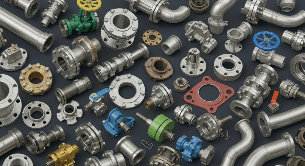
Components of a piping system
A piping system is an assembly of pressure-containing parts and their supports, joined to convey, distribute, mix, separate, meter, control or stop the flow of liquids, gases, steam or slurries. Figure 2 shows how the main components fit together in a typical process line.
Piping Components at a Glance
Function, governing standard and what the specification must state for each item
| Component | Function | Governing Standards | The Spec Must State |
|---|---|---|---|
| Pipe | Pressure-containing conduit for the fluid. | ASME B36.10M, B36.19M; ASTM A106, A333, A312, API 5L | Grade, seamless/welded, schedule per size, end prep (B16.25) |
| Fittings | Change direction, branch, size or close the line. | ASME B16.9, B16.11, MSS SP-97, MSS SP-43 | Type, radius, material, wall matching pipe |
| Flanges | Bolted, removable joints at equipment, valves and spools. | ASME B16.5-2025, B16.47-2025, B16.36, B16.48 | Type, class, facing, bore, finish |
| Valves | Isolate, regulate, prevent backflow, relieve pressure. | API 600, 602, 608, 609, 594, 623, 6D; ASME B16.34 | Type, rating, body/trim material, operator, fire-safe, low-E |
| Gaskets | Seal the flange joint. | ASME B16.20-2023, B16.21 | Type, filler, rings, thickness |
| Bolting | Clamp the joint and hold gasket stress. | ASTM A193, A194, A320, A453; ASME B18.2.1/B18.2.2 | Grade, size, length, coating |
| Supports | Carry weight, guide thermal movement, damp vibration. | MSS SP-58; project support standard | Type, material, spacing, shoes, pads |
| Expansion joints | Absorb thermal growth where loops are impractical. | EJMA Standards; ASME B31.3 App. X | Movement, cycles, pressure thrust, tie rods |
| Specialty items | Strainers, steam traps, sight glasses, spectacle blinds, hoses. | ASME B16.48; owner data sheets | Data sheet number, rating, connection |
1. Pipe
Pipe is identified by Nominal Pipe Size (NPS) and schedule. For NPS 14 and above, the NPS equals the outside diameter in inches; below that, the OD is a fixed value per size. The wall thickness is calculated from the ASME B31.3 pressure design equation, then increased for corrosion allowance and mill tolerance (12.5 percent for most seamless pipe) before the next standard schedule is chosen.
Carbon Steel Pipe OD and Wall Thickness (mm), NPS 1/2 to 24
ASME B36.10M: common schedules used in pipe classes
| NPS | DN | OD mm (in) | STD | Sch 40 | XS | Sch 80 | Sch 160 |
|---|---|---|---|---|---|---|---|
| 1/2 | 15 | 21.3 (0.840) | 2.77 | 2.77 | 3.73 | 3.73 | 4.78 |
| 3/4 | 20 | 26.7 (1.050) | 2.87 | 2.87 | 3.91 | 3.91 | 5.56 |
| 1 | 25 | 33.4 (1.315) | 3.38 | 3.38 | 4.55 | 4.55 | 6.35 |
| 1-1/2 | 40 | 48.3 (1.900) | 3.68 | 3.68 | 5.08 | 5.08 | 7.14 |
| 2 | 50 | 60.3 (2.375) | 3.91 | 3.91 | 5.54 | 5.54 | 8.74 |
| 3 | 80 | 88.9 (3.500) | 5.49 | 5.49 | 7.62 | 7.62 | 11.13 |
| 4 | 100 | 114.3 (4.500) | 6.02 | 6.02 | 8.56 | 8.56 | 13.49 |
| 6 | 150 | 168.3 (6.625) | 7.11 | 7.11 | 10.97 | 10.97 | 18.26 |
| 8 | 200 | 219.1 (8.625) | 8.18 | 8.18 | 12.70 | 12.70 | 23.01 |
| 10 | 250 | 273.1 (10.750) | 9.27 | 9.27 | 12.70 | 15.09 | 28.58 |
| 12 | 300 | 323.9 (12.750) | 9.53 | 10.31 | 12.70 | 17.48 | 33.32 |
| 14 | 350 | 355.6 (14.000) | 9.53 | 11.13 | 12.70 | 19.05 | 35.71 |
| 16 | 400 | 406.4 (16.000) | 9.53 | 12.70 | 12.70 | 21.44 | 40.49 |
| 18 | 450 | 457 (18.000) | 9.53 | 14.27 | 12.70 | 23.83 | 45.24 |
| 20 | 500 | 508 (20.000) | 9.53 | 15.09 | 12.70 | 26.19 | 50.01 |
| 24 | 600 | 610 (24.000) | 9.53 | 17.48 | 12.70 | 30.96 | 59.54 |
2. Pipe fittings
Fittings change direction, split or combine flow, change size or close a line. Large-bore process lines use butt-welded fittings for strength and inspectability; small-bore lines usually use socket-weld or threaded fittings rated by class (3000, 6000, 9000). For deeper detail see types of pipe fittings and pipe fittings dimensions and materials.
Pipe Fitting Types and Selection Rules
Butt-weld, socket-weld, threaded and branch fittings in process piping
| Fitting | Standard | Typical Size / Rating | Selection Notes |
|---|---|---|---|
| 90 deg LR elbow | ASME B16.9 | NPS 1/2 to 48, wall matched to pipe | Centre-to-end = 1.5 x NPS. Default choice for lower pressure drop. |
| 90 deg SR elbow | ASME B16.9 | Same as LR | Centre-to-end = 1.0 x NPS. Use only where space is tight; check pressure drop and erosion. |
| 45 deg elbow | ASME B16.9 | NPS 1/2 to 48 | Used for offsets and lateral routing. |
| Equal / reducing tee | ASME B16.9 | NPS 1/2 to 48 | Preferred branch where branch size is close to header size (see branch table). |
| Concentric reducer | ASME B16.9 | NPS 3/4 to 48 | Vertical lines and pump discharge. |
| Eccentric reducer | ASME B16.9 | NPS 3/4 to 48 | Pump suction, flat side up to avoid vapour pockets; flat side down on pipe racks for drainage. |
| Cap | ASME B16.9 | NPS 1/2 to 48 | Permanent closure of line ends and headers. |
| Stub end (lap joint) | ASME B16.9 / MSS SP-43 | Long or short pattern | Used with lap-joint flange; saves alloy cost on stainless and duplex lines. |
| Socket-weld fittings | ASME B16.11 | NPS 1/8 to 4; Class 3000, 6000, 9000 | Small-bore lines, usually NPS 1-1/2 and below. Leave about 1.5 mm gap before welding. |
| Threaded fittings | ASME B16.11 | NPS 1/8 to 4; Class 2000, 3000, 6000 | Utility and instrument service; avoid in cyclic, toxic (Category M) and flammable services where the spec forbids. |
| Integrally reinforced branch outlets | MSS SP-97 | Weldolet, sockolet, threadolet, elbolet | Branch much smaller than header; avoids a full tee. |
3. Flanges and flange facings
Flanges create removable joints at equipment, valves and spool breaks. The specification fixes the flange type, pressure class, facing and surface finish, and these must match the gasket and the mating equipment flange.
Flange Types, Facings and Typical Applications
ASME B16.5 (NPS 1/2-24) and B16.47 (NPS 26-60) flange selection
| Flange / Facing | Standard | Strength / Fatigue | Typical Application |
|---|---|---|---|
| Weld neck (WN) | B16.5, B16.47 | Highest; tapered hub, full-penetration butt weld | Default for hydrocarbons, high pressure, high temperature and cyclic service. |
| Slip-on (SO) | B16.5 | Lower fatigue life than WN; two fillet welds | Low-pressure utilities, cooling water, where the spec allows. |
| Socket weld (SW) | B16.5 | Good for small bore | NPS 1/2 to 3 high-pressure small-bore lines; avoid crevice-sensitive services. |
| Threaded | B16.5 | Lowest; no welding | Galvanised utility lines and areas where hot work is not allowed. |
| Lap joint (LJ) | B16.5 + stub end | Moderate; rotating ring eases bolt alignment | Stainless, duplex and lined systems needing frequent dismantling. |
| Blind | B16.5, B16.47 | Must resist full pressure as a flat plate | Closing line ends, test points and future tie-ins. |
| Orifice flange | ASME B16.36 | WN type with pressure taps | Flow metering with orifice plates (Class 300 minimum in B16.36). |
| Spectacle blind / spacer | ASME B16.48 | Matches flange rating | Positive isolation for maintenance and commissioning. |
| Raised face (RF) | B16.5 | 1.6 mm (Cl. 150/300); 6.4 mm (Cl. 400+) | Most common facing; serrated finish 3.2 to 6.3 micron Ra. |
| Flat face (FF) | B16.5 | Full-face gasket | Mating with cast iron, FRP or bronze equipment; avoids bending brittle flanges. |
| Ring-type joint (RTJ) | B16.5, B16.20 | Metal-to-metal seal in a groove | Class 900 and above, high-temperature hydrogen and critical hydrocarbon service. |
4. Pressure-temperature ratings
A flange class is not a pressure. A Class 300 flange does not mean 300 psi or 300 bar; it means a set of allowable pressures that fall as temperature rises, different for each material group. The table and chart below show the ratings for the most common carbon steel group.
ASME B16.5 Pressure-Temperature Ratings, Group 1.1 (bar g)
Carbon steel: A105, A216 WCB, A350 LF2 Cl.1, A515 Gr 70, A516 Gr 70
| Temp (deg C) | Class 150 | Class 300 | Class 600 | Class 900 | Class 1500 | Class 2500 |
|---|---|---|---|---|---|---|
| -29 to 38 | 19.6 | 51.1 | 102.1 | 153.2 | 255.3 | 425.5 |
| 50 | 19.2 | 50.1 | 100.2 | 150.4 | 250.6 | 417.7 |
| 100 | 17.7 | 46.6 | 93.2 | 139.8 | 233.0 | 388.3 |
| 150 | 15.8 | 45.1 | 90.2 | 135.2 | 225.4 | 375.6 |
| 200 | 13.8 | 43.8 | 87.6 | 131.4 | 219.0 | 365.0 |
| 250 | 12.1 | 41.9 | 83.9 | 125.8 | 209.7 | 349.5 |
| 300 | 10.2 | 39.8 | 79.6 | 119.5 | 199.1 | 331.8 |
| 350 | 8.4 | 37.6 | 75.1 | 112.7 | 187.8 | 313.0 |
| 375 | 7.4 | 36.4 | 72.7 | 109.1 | 181.8 | 303.1 |
| 400 | 6.5 | 34.7 | 69.4 | 104.2 | 173.6 | 289.3 |
| 425 | 5.5 | 28.8 | 57.5 | 86.3 | 143.8 | 239.7 |
| 450 | 4.6 | 23.0 | 46.0 | 69.0 | 115.0 | 191.7 |
5. Valves
Valves isolate, regulate, divert, prevent backflow or relieve pressure. The pipe class assigns a valve data-sheet code to each type and size range, and the data sheet carries the full requirements.
Industrial Valve Types and Their Standards
What each valve does and which standard the PMS should call up
| Valve | Primary Function | Design Standard | Spec Notes |
|---|---|---|---|
| Gate | On/off isolation, full bore, low pressure drop | API 600 (bolted bonnet, NPS 1 and larger); API 602 (compact, NPS 4 and smaller); API 603 (corrosion-resistant) | Not for throttling. Specify trim number (e.g. Trim 8 = 13Cr + hardfaced seats). |
| Globe | Throttling and flow regulation | API 623; API 602 for small bore; ASME B16.34 | Higher pressure drop; install with flow under the disc unless the spec states otherwise. |
| Ball | Quick quarter-turn shut-off | API 608 (metal ball); API 6D (pipeline); ISO 17292 | Fire-safe to API 607 / ISO 10497 for hydrocarbons; floating vs trunnion by size and class. |
| Butterfly | Isolation and throttling in large sizes | API 609 (Category A concentric, Category B high-performance) | Compact and light; check disc clearance with lined pipe and wafer bolting. |
| Check | Prevents reverse flow | API 594 (wafer, lug, double-flanged); API 602; API 6D | Swing, dual-plate, piston or lift type; verify minimum flow for full opening. |
| Plug | Quarter-turn isolation, multi-port diversion | API 599; API 6D | Lubricated or sleeved; good for slurries and viscous fluids. |
| Pressure relief | Overpressure protection | ASME Section VIII / XIII, API 526, API 520/521 | Sized for the governing relief case; inlet loss below 3 percent of set pressure. |
| All steel valves | Pressure-temperature rating and wall thickness | ASME B16.34-2025 | Standard, Special or Limited Class ratings. |
| Testing & emissions | Shell, seat and fugitive-emission tests | API 598; API 6D; ISO 15848-1; API 624 / API 641 | Low-E valves increasingly required by owner specs and emission regulations. |
6. Gaskets
The gasket is the part of the joint that actually seals, so its type must suit the fluid, temperature, pressure class and flange facing.
Flange Gasket Selection Guide
Common gasket types, their standards and service limits
| Gasket Type | Standard | Typical Rating / Service | Selection Notes |
|---|---|---|---|
| Compressed non-asbestos fibre (CNAF) | ASME B16.21 | Class 150-300, water, air, low-temperature utilities | Simple and low cost; check temperature and steam limits of the brand. |
| PTFE sheet / expanded PTFE | ASME B16.21 | Class 150-300, aggressive chemicals | Excellent chemical resistance; prone to creep, so prefer filled or expanded grades. |
| Flexible graphite laminated | ASME B16.21 | Class 150-600, steam and hydrocarbons | Good at high temperature; use with stainless insert for handling. |
| Spiral-wound | ASME B16.20-2023 | Class 150-2500, hydrocarbons, steam, most process service | Inner ring required with PTFE filler and for larger sizes in Class 900, 1500 and 2500; many owner specs require inner rings on all sizes. |
| Kammprofile (grooved metal) | ASME B16.20-2023 | Class 150-2500, heat exchangers and difficult joints | Low seating stress, good recovery; graphite or PTFE facing layers. |
| Ring-type joint (R, RX, BX) | ASME B16.20; API 6A (BX) | Class 900-2500 and wellhead service | Ring must be softer than the flange groove (e.g. soft iron, 4-6 percent Cr, SS316). |
| Insulating gasket kit | Manufacturer standard | Cathodic protection breaks, dissimilar metals | Includes insulating sleeves and washers for each bolt. |
7. Bolting
Stud bolts and nuts provide the load that compresses the gasket. Their grade must suit the flange temperature, the environment and, in sour service, hardness limits. Use the Bolt Torque and Flange Joint Integrity Calculator to estimate assembly torque.
Stud Bolt and Nut Combinations for Flanged Joints
Common ASTM bolting grades and typical service ranges
| Stud / Nut | Material | Typical Service Range | Use |
|---|---|---|---|
| A193 B7 / A194 2H | Cr-Mo alloy steel | About -29 to 425 C (higher with care) | General refinery and process service with carbon steel flanges. |
| A193 B7M / A194 2HM | Cr-Mo, hardness-limited | About -29 to 425 C | Sour (wet H2S) service to NACE MR0175 / ISO 15156. |
| A320 L7 / A194 Gr 7 (or 4) | Cr-Mo, impact tested | Down to about -101 C | Low-temperature carbon steel systems (A333, A350 LF2). |
| A193 B16 / A194 Gr 4 or 7 | Cr-Mo-V alloy | Up to about 540 C | High-temperature steam and hot oil. |
| A193 B8M Cl.2 / A194 8M | Strain-hardened 316 stainless | Cryogenic to moderate temperature | Stainless and cryogenic systems; corrosive environments. |
| A453 Gr 660 / matching nut | Precipitation-hardened austenitic | High temperature, about 540-650 C | High-temperature alloy and stainless flanges. |
| Coatings | PTFE, zinc-nickel, hot-dip galvanising | Ambient to coating limit | Corrosion protection offshore and in coastal plants; check torque factor. |
8. Supports, expansion joints and specialty items
These items sit outside the pressure class tables but are still controlled by the specification or its companion standards. Supports manage weight and thermal movement; specialty items protect equipment and allow isolation. Estimate support spans with the Pipe Support Spacing Calculator.
Supports, Expansion Joints and Specialty Items
Components outside the pressure class that still belong in the specification
| Item | Purpose | Reference | Spec Points |
|---|---|---|---|
| Resting shoe / guide | Carries weight and limits lateral movement | MSS SP-58; project support standard | Shoe height for insulation, PTFE or graphite slide plates |
| Anchor / line stop | Fixes a point against thermal movement | Stress analysis output | Design loads from the stress isometric |
| Spring hanger | Supports weight while allowing vertical travel | MSS SP-58 | Variable or constant load; travel and load variation within limits |
| Clamps and U-bolts | Secure small-bore and utility lines | MSS SP-58 | Material compatible with pipe; avoid on thin-wall stainless without liners |
| Expansion joint (bellows) | Absorbs axial, lateral and angular movement | EJMA Standards; ASME B31.3 App. X | Design cycles, pressure thrust, tie rods, internal sleeves |
| Y / basket strainer | Protects pumps, meters and control valves | Body rating per ASME B16.34 | Mesh size, open area ratio, drain and vent |
| Steam trap | Removes condensate without losing steam | Manufacturer data; ISO 6704 classification | Thermodynamic, float or bucket type to suit load |
| Sight glass / flow indicator | Visual confirmation of flow | Manufacturer data sheet | Glass type and guard rated for the class |
| Spectacle blind | Positive isolation | ASME B16.48 | Rated to the flange class; turned position shown on the P&ID |
Material selection by service
Material choice follows the fluid, temperature and corrosion mechanism. The table below summarises the materials found in most pipe classes. For grade-level data, see carbon steel piping materials, stainless steel in process piping, alloy steel in piping and non-metallic piping materials.
Piping Material Selection by Service
Typical base materials used in pipe classes and their practical limits
| Service | Typical Pipe Material | Practical Temperature Range | Watch-outs |
|---|---|---|---|
| General hydrocarbons, steam, water | ASTM A106 Gr B / API 5L Gr B (seamless) | -29 to about 425 C | Graphitisation risk above about 425 C for long exposure. |
| Low temperature | ASTM A333 Gr 6 | Down to -46 C (impact tested) | Fittings A420 WPL6, flanges A350 LF2. |
| High temperature, steam | ASTM A335 P11, P22, P91 | Up to about 550-600 C+ (grade dependent) | PWHT and hardness control; P91 needs strict heat treatment. |
| Corrosive and cryogenic | ASTM A312 TP304L / TP316L | -196 to about 425 C for L grades | Chloride stress corrosion cracking above about 60 C. |
| Seawater, produced water, chlorides | ASTM A790 duplex S32205 / super duplex S32750 | -46 to about 250-300 C | 475 C embrittlement limits upper temperature; ferrite control in welds. |
| Large-diameter water and gas | ASTM A671 / A672 EFW; API 5L PSL2 | Ambient service | Radiography of long seams; coating and lining. |
| Seawater (marine) | 90/10 Cu-Ni (ASTM B466 / EEMUA 234) | Ambient | Velocity limit about 3.5 m/s to prevent erosion. |
| Water, chemicals, buried service | HDPE PE100 (ISO 4427), PVC-U, CPVC, GRE | Up to about 60 C (PE/PVC), about 93 C (CPVC) | Pressure de-rating with temperature; UV protection; support spacing. |
| Sour service (wet H2S) | Carbon steel to NACE MR0175 / ISO 15156 | Per base material | Hardness limits on base metal and welds, HIC-resistant plate for large bore. |
Applicable codes and standards
The specification must name each standard and its edition. Editions change: for example, ASME B16.5 and B16.34 were reissued in 2025 and B16.9 in 2024. The list below was checked in October 2026.
Applicable Codes and Standards for Piping Specifications
Latest editions verified October 2026; always confirm the edition named in the contract
| Standard | Scope | Edition Status |
|---|---|---|
| ASME B31.3 | Process piping: design, materials, fabrication, examination, testing | 2024 (current) |
| ASME B31.1 | Power piping: boiler external piping and power plant systems | Current edition per contract |
| ASME B31.4 / B31.8 | Liquid and gas pipeline transportation systems | Current edition per contract |
| ASME B36.10M | Welded and seamless wrought steel pipe dimensions | 2022 |
| ASME B36.19M | Stainless steel pipe dimensions | 2022 |
| ASME B16.5 | Pipe flanges and flanged fittings, NPS 1/2 through 24 | 2025 |
| ASME B16.47 | Large-diameter steel flanges, NPS 26 through 60 | 2025 |
| ASME B16.9 | Factory-made wrought butt-welding fittings | 2024 |
| ASME B16.11 | Forged fittings, socket-welding and threaded | Current edition per contract |
| ASME B16.20 | Metallic gaskets: spiral-wound, ring-joint, grooved | 2023 |
| ASME B16.21 | Non-metallic flat gaskets for pipe flanges | Current edition per contract |
| ASME B16.34 | Valves: flanged, threaded and welding end | 2025 |
| ASME B16.25 / B16.48 | Butt-welding ends / line blanks | Current edition per contract |
| MSS SP-58 / SP-97 | Pipe hangers and supports / branch outlet fittings | Current edition per contract |
| API 600, 602, 608, 609, 594, 6D | Steel gate, compact, ball, butterfly, check and pipeline valves | Current edition per contract |
| API 598 / ISO 15848-1 | Valve inspection and testing / fugitive emissions | Current edition per contract |
| ASME PCC-1 | Bolted flange joint assembly | Current edition per contract |
| NACE MR0175 / ISO 15156 | Materials for H2S-containing (sour) environments | Current edition per contract |
Inspection and testing
The specification links each class to its examination and test requirements, so the extent of NDE and the test method are known before fabrication starts. See also pipe inspection, testing and marking.
Inspection and Testing Requirements for Piping Components
Typical ASME B31.3 requirements that the specification must reference
| Activity | Requirement (ASME B31.3 unless noted) | When It Applies |
|---|---|---|
| Material certification | Mill test certificate, normally EN 10204 Type 3.1 | All pressure parts |
| Positive material identification (PMI) | XRF or OES check of alloy elements (API 578) | Alloy and stainless systems; owner may extend to carbon steel residuals |
| Visual examination | Per para. 341.4 for all welds and components | Every fabricated item |
| RT/UT of girth welds | Not less than 5 percent random for Normal Fluid Service | Normal service (higher for Category M, severe cyclic and high pressure) |
| 100 percent RT/UT | Required for severe cyclic and High Pressure (Chapter IX) service | Critical services as listed in the spec |
| Hydrostatic leak test | Not less than 1.5 x design pressure, corrected by the stress ratio at test vs design temperature (para. 345.4) | Default leak test; minimum 10 min hold |
| Pneumatic leak test | 1.1 x design pressure (para. 345.5) with stepwise pressurisation | Only where water is not acceptable; needs safety review |
| Initial service leak test | Check at operating conditions (para. 345.7) | Category D fluid service only, if the owner agrees |
| Hardness testing | Base metal and welds within ISO 15156 limits (typically 22 HRC / 250 HV for carbon steel) | Sour service and PWHT verification |
| Valve testing | Shell and seat tests to API 598 or API 6D | Every valve before dispatch |
How to develop a piping specification: 8 steps
- Collect process design data. Take fluid, design pressure, design and minimum temperatures, upset cases and contaminants (H2S, CO2, chlorides, oxygen) from the process line list.
- Fix the code and fluid service. Confirm ASME B31.3, B31.1 or a pipeline code governs, and assign the fluid service category: Normal, Category D, Category M, High Pressure or Elevated Temperature.
- Choose material and corrosion allowance. Use the corrosion study to select the base material and a corrosion allowance that covers the design life.
- Select the pressure class. Pick the lowest ASME B16.5 or B16.47 class whose rating covers every pressure-temperature point for that material group.
- Size the wall thickness. Apply the B31.3 pressure design equation, add allowances, correct for mill tolerance and choose the next standard schedule.
- Specify fittings, flanges, gaskets and bolting. Call up standards, materials, end connections, flange facing, gasket type and bolting grade for each size band.
- Define valves and the branch table. Assign valve data-sheet codes by size and build the header-branch matrix.
- Add notes, review and issue. Add NDE, PWHT, impact test, hardness and cleaning notes; run a multi-discipline review and issue under revision control.
Common mistakes and best practices
- Mixing STD and Sch 40 above NPS 10. They are different walls from NPS 12 upward. Write the exact designation on the class sheet.
- Ignoring the minimum design metal temperature. Auto-refrigeration on depressurisation can take carbon steel below its impact-tested limit; use A333 or impact-tested material where needed.
- Mismatched B16.47 series. Series A and B large-diameter flanges do not bolt together. State the series on vessel, valve and piping data sheets.
- Spiral-wound gaskets without inner rings. Inner rings stop buckling and protect the winding; most owners now require them on all sizes.
- Slip-on flanges in cyclic service. Use weld neck flanges where thermal or pressure cycling is expected.
- Uncontrolled specification breaks. Show every class change on the P&ID and use the stricter class at the break joint.
- Outdated editions. Re-check the editions in your PMS whenever a new project starts.
Related Aienginear guides and calculators
Frequently asked questions
What is a piping specification?
A piping specification is a project document that lists the approved pipe, fittings, flanges, valves, gaskets and bolting for each service, together with the pressure-temperature limits, corrosion allowance, governing code and fabrication notes. It turns code requirements into a buyable, buildable list of components.
What is the difference between a piping specification and a pipe class?
The piping material specification (PMS) is the complete document for a project. A pipe class is one sheet inside it, covering one combination of material, rating and corrosion allowance (for example Class 150 carbon steel with 1.5 mm corrosion allowance). Each line on the P&ID is assigned to one pipe class.
What are the main components of a piping system?
The main components are pipe, fittings (elbows, tees, reducers, caps), flanges, valves, gaskets, bolting, branch connections, pipe supports, expansion joints and specialty items such as strainers, steam traps and spectacle blinds.
Which standards apply to piping specifications?
ASME B31.3 (process piping, 2024 edition) or B31.1 (power piping) sets the design rules. Components follow ASME B16.5 and B16.47 (flanges, 2025), B16.9 (butt-weld fittings, 2024), B16.11 (forged fittings), B16.20 and B16.21 (gaskets), B16.34 (valves, 2025) and B36.10M/B36.19M (pipe, 2022), plus ASTM material and API valve standards.
How do you select the flange pressure class?
Find the material group of the flange (for example Group 1.1 for A105), then choose the lowest ASME B16.5 class whose rated pressure at the design temperature is equal to or higher than the design pressure. For example, 35 barg at 300 C needs Class 300, because Class 150 is rated only 10.2 barg at that temperature.
Why is a weld neck flange preferred over a slip-on flange?
A weld neck flange has a tapered hub and a full-penetration butt weld, giving better fatigue strength and easier radiography. Slip-on flanges are cheaper and easier to align but have a lower fatigue life, so most specifications limit them to low-pressure utility service.
Who prepares the piping specification?
The piping material engineer of the EPC contractor or the owner prepares it from process data, the corrosion study and the governing code. Process, materials, mechanical, inspection and operations teams review it before it is issued for design and procurement.
Is Schedule 40 the same as STD wall thickness?
Only up to NPS 10. From NPS 12 upward STD stays at 9.53 mm, while Schedule 40 becomes thicker (10.31 mm at NPS 12). Likewise XS and Schedule 80 are the same only up to NPS 8.
Test your knowledge: piping specifications and components quiz
Ten questions based on this guide. Select your answers, then press Check my answers to see your score and explanations.
1. Which document lists every approved component for one combination of material, rating and corrosion allowance?
2. Up to which NPS are STD and Schedule 40 wall thicknesses identical?
3. What is the rated pressure of a Class 150, Group 1.1 flange at 38 C?
4. Which flange facing uses a metal ring seated in machined grooves?
5. Which standard covers factory-made wrought butt-welding fittings?
6. Which valve type should NOT be used for throttling?
7. Which pipe material is normally used for -46 C service?
8. What is the standard hydrostatic test pressure basis in ASME B31.3?
9. Which bolting combination is used for low-temperature carbon steel systems?
10. When must a spiral-wound gasket with PTFE filler have an inner ring per ASME B16.20?
References: ASME B31.3-2024 Process Piping; ASME B16.5-2025; ASME B16.47-2025; ASME B16.9-2024; ASME B16.11; ASME B16.20-2023; ASME B16.34-2025; ASME B36.10M-2022; ASME B36.19M-2022; ASME PCC-1; MSS SP-58; API 598, 600, 602, 608, 609, 594, 6D; NACE MR0175/ISO 15156. Table values are summarised for education; always use the purchased standard for design.
Last reviewed: October 10, 2026 by Muhammad Raza, Aienginear. Found an error or need a table in another format? Use the contact page and we will update it.

Written by Muhammad Raza
Founder of Aienginear. Engineering and digital solutions professional with 26+ years managing projects, plant shutdowns and turnarounds in oil & gas, petrochemical and power generation.