
PIPING ENGINEERING GUIDE
What are pipe fittings?
Pipe fittings are the components that join lengths of pipe and make a piping system work: they change direction (elbows and bends), split or merge flow (tees, crosses, laterals and olets), change size (reducers, swages and bushings), close an end (caps and plugs), and make joints (couplings, unions, nipples and stub ends).
In process plants, butt-weld fittings for NPS ½–48 are made to ASME B16.9-2024, forged socket-weld and threaded fittings to ASME B16.11-2021, and branch outlets to MSS SP-97. The piping class (PMS) chooses the type, material, wall thickness and end connection for each line.
What pipe fittings do in a piping system
A pipe on its own only carries fluid in a straight line. Every turn, branch, size change, dead end and maintenance break in a plant needs a fitting, and each fitting adds a weld or joint, a small pressure loss and an inspection point. Good piping design uses as few fittings as practical, of the right type, in the right orientation.
Fittings are pressure-retaining parts. A butt-weld fitting bought to ASME B16.9 is designed so that its burst strength is at least that of the straight seamless pipe of the same material and wall it is marked for. That is why a B16.9 fitting is ordered by size, schedule and material grade — not by a pressure class like a flange.
Aienginear · Table 1
Pipe fitting functions at a glance
Pick the fitting family from the job it has to do
| Job in the system | Fitting family | Typical examples | Main standard |
|---|---|---|---|
| Change direction | Elbows, bends, returns | 90° LR elbow, 45° elbow, 5D bend, 180° return | ASME B16.9, B16.49 (bends) |
| Split or combine flow | Tees, crosses, laterals | Equal tee, reducing tee, barred tee, 45° lateral | ASME B16.9 |
| Small branch off a header | Branch outlets (olets) | Weldolet, sockolet, threadolet, nippolet | MSS SP-97 |
| Change line size | Reducers, swages, bushings | Concentric / eccentric reducer, swage nipple | ASME B16.9, MSS SP-95, B16.11 |
| Close a line end | Caps, plugs, bull plugs | BW cap, hex-head plug, bull plug | ASME B16.9, B16.11, MSS SP-95 |
| Join pipe or make a breakable joint | Couplings, unions, nipples | Full coupling, 3-piece union, TBE nipple | ASME B16.11, MSS SP-83 |
| Interface with a lap-joint flange | Stub ends | Long-pattern (B16.9) and short-pattern (MSS SP-43) | ASME B16.9, MSS SP-43 |
| Instrument, vent or drain point | Half coupling, olet, nippolet | Pressure gauge tap, high-point vent | ASME B16.11, MSS SP-97 |
Engineer’s note
Valves, flanges, gaskets, strainers, steam traps and expansion joints are piping components, but they are not fittings in the B16.9/B16.11 sense. They have their own standards (for example ASME B16.5, B16.34 and B16.20) and are covered in separate Aienginear guides.
How pipe fittings are classified
Engineers group fittings in four practical ways. The same tee can be described as a branch fitting (function), a wrought butt-weld fitting (construction), a BW fitting (end connection) and an A234 WPB fitting (material). A complete purchase description uses all four.
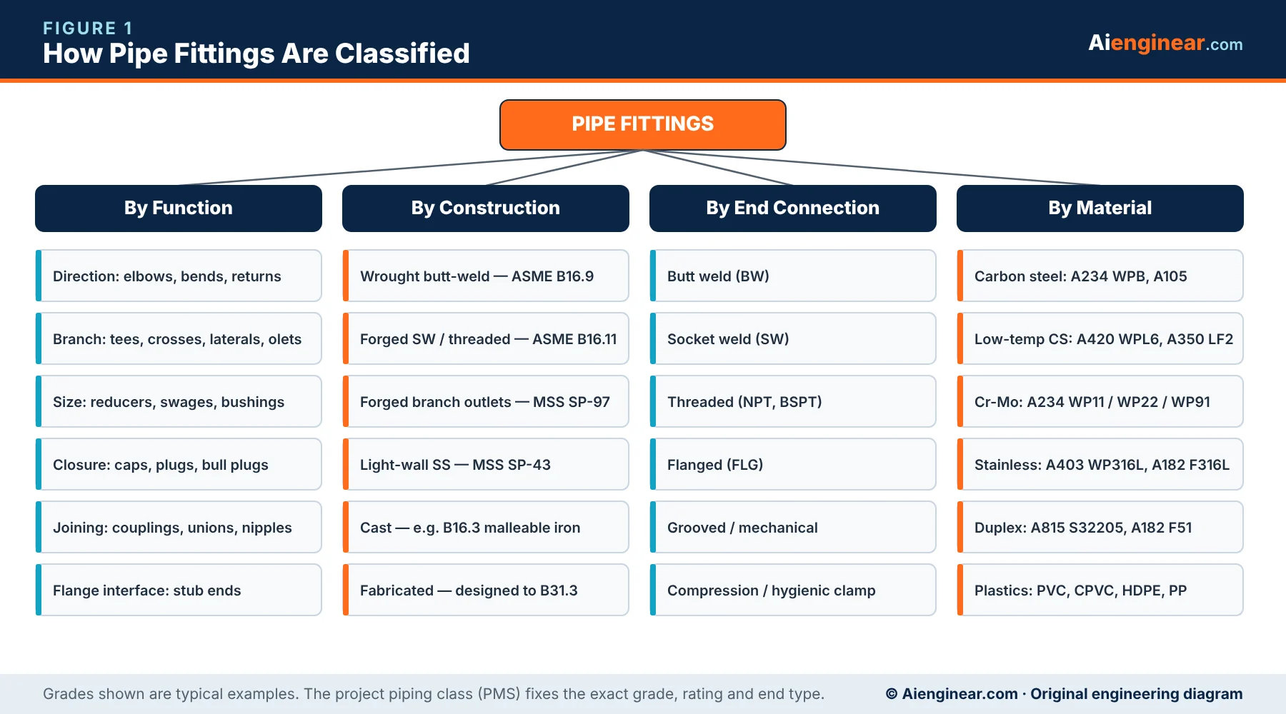
1. By construction (how the fitting is made)
- Wrought butt-weld fittings — formed from seamless pipe, welded pipe or plate, then heat treated and bevelled. Covered by ASME B16.9 (dimensions) and ASTM A234, A403, A420, A815 or A860 (material). Welded-construction fittings carry a “W” in the grade marking, for example WPB-W. Read our pipe fittings manufacturing process guide for the forming routes.
- Forged fittings — machined from forgings or bar for small bore, socket-weld and threaded service. Covered by ASME B16.11 with forging grades such as ASTM A105, A182 and A350.
- Forged branch outlets — integrally reinforced olets to MSS SP-97.
- Cast fittings — cast iron, malleable iron and some alloy fittings for utilities and special services.
- Fabricated fittings — mitre bends, fabricated tees and laterals, pressure-designed under ASME B31.3 and examined like any other weld.
2. By end connection
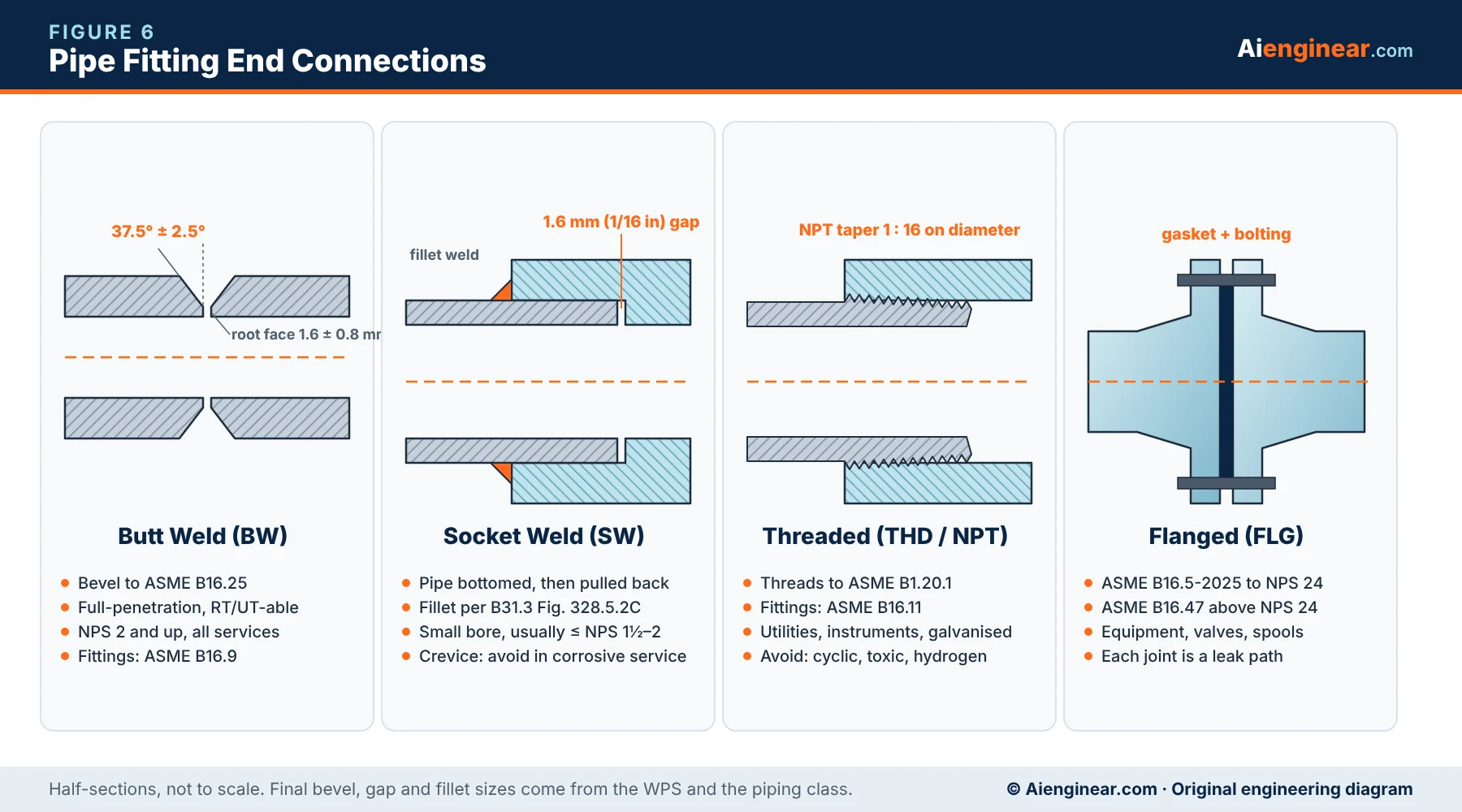
Butt weld, socket weld, threaded, flanged, grooved (mechanical) and compression or hygienic clamp. End connections are explained with sketches below.
3. By pressure basis — schedule or class?
This is where many guides go wrong. Butt-weld fittings have no pressure class. They are rated by matching the schedule (wall) and material of the connected pipe. Forged B16.11 fittings use Classes 2000, 3000, 6000 and 9000, which are linked to pipe schedules, not to psi. Flanges use Classes 150–2500 under ASME B16.5-2025. Mixing these three systems up is a common error on material requisitions.
Pipe fitting standards and current editions
Always quote the edition required by the contract, then confirm it against the publisher. The editions below were checked on 16 October 2026.
Aienginear · Table 2
Pipe fitting standards (2026 check)
Dimensional, material and design documents engineers cite most often
| Document | Edition | Scope | Engineer’s note |
|---|---|---|---|
| ASME B16.9 | 2024 | Factory-made wrought butt-welding fittings, NPS ½–48 | Includes LR and SR elbows, returns, tees, crosses, reducers, caps, long-pattern stub ends |
| ASME B16.11 | 2021 | Forged fittings, socket-welding and threaded | Classes 2000/3000/6000 threaded; 3000/6000/9000 socket weld |
| ASME B16.28 | Withdrawn | Former SR elbows and returns | Content moved into B16.9; do not cite B16.28 on new specifications |
| ASME B16.25 | Current edition | Butt-welding end preparation | Bevel 37.5° ± 2.5°, root face 1.6 ± 0.8 mm for standard ends |
| ASME B16.49 | Current edition | Factory-made induction bends for transportation and distribution systems | Used for 3D/5D pipeline bends |
| ASME B16.5 | 2025 | Pipe flanges and flanged fittings, NPS ½–24 | Classes 150 to 2500 |
| ASME B1.20.1 | Current edition | Pipe threads, general purpose (NPT) | Taper 1 in 16 on diameter |
| ASME B31.3 | 2024 | Process piping design, fabrication and testing | Branch reinforcement (304.3), mitre bends (304.2.3), joint limits (Chapter V) |
| MSS SP-97 | 2019 | Integrally reinforced forged branch outlet fittings | Weld, socket and threaded outlets |
| MSS SP-95 | 2024 | Swage(d) nipples and bull plugs | Concentric and eccentric swages |
| MSS SP-75 | 2025 | High-strength wrought butt-welding fittings | Pipeline grades WPHY 42–70 |
| MSS SP-83 | Current edition | Class 3000 and 6000 pipe unions, SW and threaded | Steel unions |
| MSS SP-43 | Current edition | Light-wall stainless butt-weld fittings, short-pattern stub ends | Sch 5S / 10S service |
| MSS SP-25 | Current edition | Marking system for valves, fittings, flanges and unions | Defines what must be stamped |
| ASTM A960/A960M | A960-25a | Common requirements for wrought steel fittings | Ordering, heat treatment, supplementary requirements |
“Current edition” means confirm the year on the publisher’s site before quoting it. The contract edition always governs.
Pipe fitting materials and grades
A fitting must match the pipe it is welded to in material group, strength and toughness. Wrought butt-weld fittings use “WP” (wrought product) grades; forged small-bore fittings use forging grades. The table pairs the common grades.
Aienginear · Table 3
Fitting material grades by pipe material
Typical matching grades; the PMS gives the final selection
| Service / pipe | Pipe example | Butt-weld fitting | Forged fitting (SW/THD) | Typical use |
|---|---|---|---|---|
| Carbon steel | A106 Gr B, API 5L B | ASTM A234 WPB | ASTM A105 | Water, steam, hydrocarbons to about 425 °C |
| Low-temperature CS | A333 Gr 6 | ASTM A420 WPL6 | ASTM A350 LF2 | Down to −46 °C with impact testing |
| Cr-Mo alloy | A335 P11 / P22 / P91 | ASTM A234 WP11 / WP22 / WP91 | ASTM A182 F11 / F22 / F91 | High-temperature steam and hydrogen |
| Austenitic stainless | A312 TP316L | ASTM A403 WP316L | ASTM A182 F316L | Corrosive, cryogenic, hygienic |
| Duplex stainless | A790 S32205 | ASTM A815 WPS32205 | ASTM A182 F51 / F60 | Chlorides, seawater, offshore |
| Super duplex | A790 S32750 | ASTM A815 WPS32750 | ASTM A182 F53 | Seawater and firewater offshore |
| Pipeline high strength | API 5L X52–X70 | MSS SP-75 WPHY 52–70 | — | Transmission pipelines |
| Nickel alloys | B444 (625), B622 (C-276) | ASTM B366 | ASTM B564 | Severe corrosion, high temperature |
| Thermoplastics | PVC, CPVC, HDPE, PP | Solvent-weld / fusion fittings | — | Water, chemicals, buried services |
Grades are common pairings, not a substitute for the project piping material specification. For more detail see our guides to stainless steel and non-metallic piping materials.
Pipe fitting end connections
The end connection decides how the fitting is joined, how it is inspected, and how likely it is to leak. Large-bore process lines are almost always butt-welded; small bore is socket-welded or threaded depending on the fluid and the piping class.
Aienginear · Table 4
End connection comparison
Where each joint type is normally used
| End type | Typical size | Strength / leak tightness | Inspection | Typical service | Avoid in |
|---|---|---|---|---|---|
| Butt weld (BW) | NPS 2 and larger | Highest; full-penetration | RT or UT, PT/MT | All process services | — |
| Socket weld (SW) | NPS ½–2 (up to 4) | High; fillet weld | PT/MT of fillet | Small-bore process, utilities | Crevice-corrosive and severe cyclic service |
| Threaded (NPT) | NPS ⅛–4 | Moderate; thread is a leak path | Visual, leak test | Instrument air, water, galvanised utilities | Toxic, flammable cyclic, hydrogen, vibration |
| Flanged | All sizes | Good; depends on gasket and bolting | Bolt-up and leak test | Equipment, valves, removable spools | Buried lines and needless joints |
| Grooved / mechanical | NPS 1–24+ | Good at low pressure | Visual | Fire protection, HVAC water | Hydrocarbon process lines |
| Compression / clamp | Tubing sizes | Good when correctly assembled | Gap gauge, leak test | Instrument tubing, hygienic lines | Large bore |
Socket-weld gap
Before a socket weld is made, the pipe is bottomed in the socket and pulled back about 1.6 mm (1/16 in). The gap lets the pipe expand during welding; without it the fillet weld can crack. Fillet size follows ASME B31.3 Fig. 328.5.2C.
Pipe elbows and bends
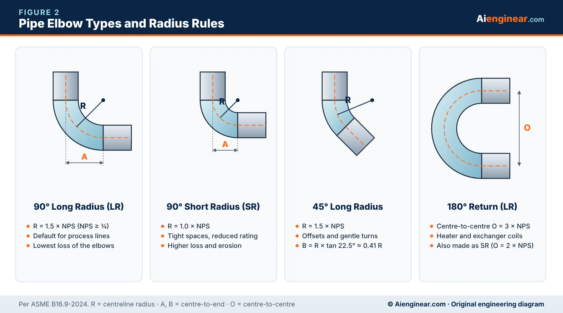
Elbows are the most used fittings in any plant. They are specified by angle (45°, 90°, 180°), radius (long or short), size, wall and material. The radius is measured to the centreline of the fitting.
Long-radius (LR) elbow
An LR elbow has a centreline radius of 1.5 × NPS for NPS ¾ and larger. For an NPS 8 LR 90° elbow the centre-to-end dimension is 12 in (305 mm). LR is the default choice in process piping because the gentler turn gives lower pressure drop, less erosion and easier pigging or cleaning.
Short-radius (SR) elbow
An SR elbow has a radius of 1.0 × NPS, so an NPS 8 SR elbow is 8 in (203 mm) centre-to-end. Use SR only where space forces it. ASME B16.9 notes that SR elbows may have a lower pressure rating than the matching straight pipe, so check the rating in the piping class before using them in high-pressure lines.
45° elbow and 180° return
A 45° elbow is used for offsets and gentle turns; its centre-to-end distance is the radius × tan 22.5°, about 0.41 R. A 180° return reverses flow and is common in fired-heater coils, exchanger U-loops and tracer manifolds. An LR return has a centre-to-centre distance of 3 × NPS; an SR return is 2 × NPS.
Aienginear · Table 5
Long-radius vs short-radius elbow
Comparison for the same size and wall
| Feature | Long radius (LR) | Short radius (SR) |
|---|---|---|
| Centreline radius | 1.5 × NPS (NPS ≥ ¾) | 1.0 × NPS |
| Example, NPS 8 90° centre-to-end | 12 in / 305 mm | 8 in / 203 mm |
| Pressure drop (Crane K, NPS 6) | ≈ 0.21 (14 fT) | ≈ 0.30 (20 fT) |
| Erosion and turbulence | Lower | Higher |
| Pressure rating | Equal to matching pipe | May be lower — check B16.9 and the class |
| Piggable | Generally no (needs 3D–5D bends) | No |
| Typical use | Default for process and utility lines | Tight skids, modules and congested racks |
Pipe bends, induction bends and mitre bends
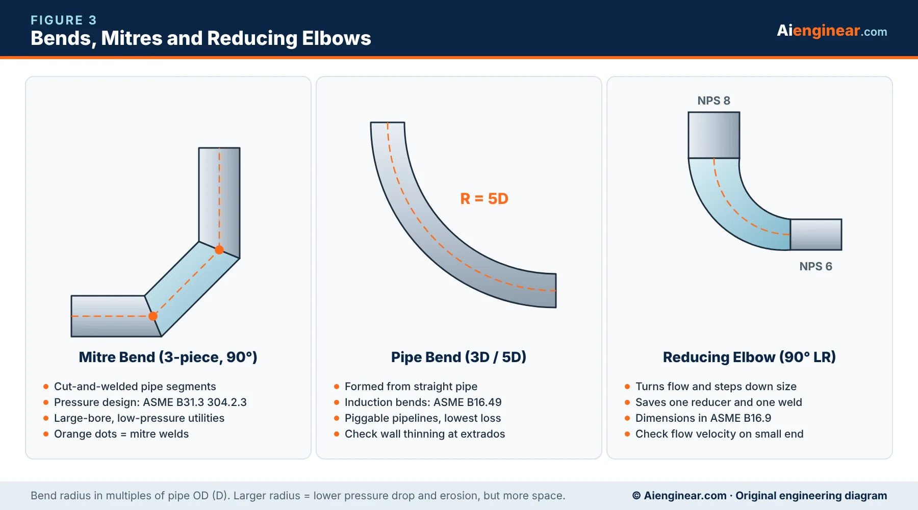
A pipe bend is made by bending straight pipe, usually to a radius of 3D, 5D or larger. Factory induction bends for pipelines follow ASME B16.49. Bends remove a weld at each end compared with elbows and allow pigging, but they need space and are checked for wall thinning on the outside (extrados) and ovality.
A mitre bend is made by cutting and welding pipe segments. It is cheap for very large, low-pressure lines such as cooling water and flare headers, but it creates turbulence and stress concentration. ASME B31.3 paragraph 304.2.3 gives the pressure design rules and limits; many piping classes restrict mitres to low-pressure, non-cyclic service.
A reducing elbow turns the flow and reduces size in one piece, saving a reducer and a weld. LR reducing elbows are listed in ASME B16.9.
Pipe tees, crosses and laterals
Tees make branch connections. Because the reinforcement is built into the fitting, a B16.9 tee needs no separate branch calculation when it is used within its rating. The size is given run × run × branch, for example 12 × 12 × 6.
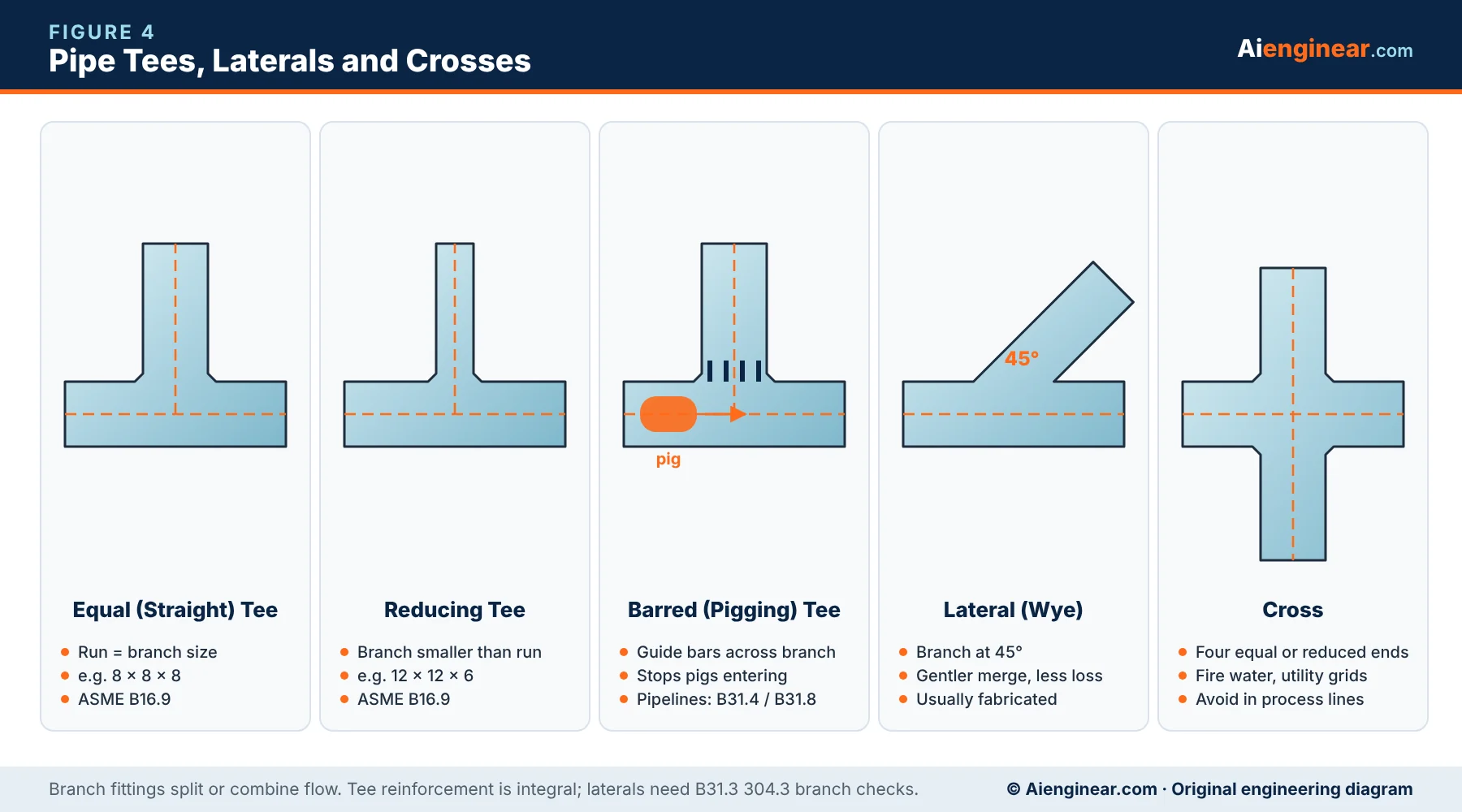
- Equal (straight) tee — all three ends the same size. Used for splitting flow and for full-size branches.
- Reducing tee — the branch is smaller than the run. The usual choice when the branch is about half the run size or larger; below that, an olet is normally cheaper.
- Barred tee — a tee with guide bars across the branch opening so pipeline pigs stay in the run. Used in pigged oil and gas lines designed to ASME B31.4 or B31.8.
- Lateral (wye) — the branch joins at 45°, giving a gentler merge for slurries, drains and gravity lines. Laterals are not covered by B16.9 and are usually fabricated, so their reinforcement must be checked to ASME B31.3 304.3.
- Cross — a four-way fitting. Common in fire-water grids; avoided in process lines because the colliding flows add pressure loss and the crotch areas are highly stressed.
Aienginear · Table 6
Tee type selection
Choosing between tee types
| Tee type | Branch size | Flow pattern | Best for | Watch out for |
|---|---|---|---|---|
| Equal tee | Same as run | Even split or full-size branch | Headers, distribution, bypasses | Higher branch K (≈ 60 fT) than run |
| Reducing tee | Smaller than run | Main flow through run | Branches ≥ about ½ run size | Order exact run × branch combination |
| Barred tee | Usually ≥ 50% of run | Pig passes the branch | Pigged pipelines | Bar welds and bar spacing per pipeline spec |
| Lateral (45°) | Equal or reduced | Smooth merge | Slurry, drains, gravity flow | Fabricated; needs branch reinforcement check |
| Cross | Equal or reduced | Colliding flows | Fire water, utility grids | Avoid in process and cyclic service |
Pipe reducers and swages
Reducers join two line sizes. A concentric reducer keeps the same centreline on both ends; an eccentric reducer has one flat side, and the centrelines are offset by half the difference in inside diameters.
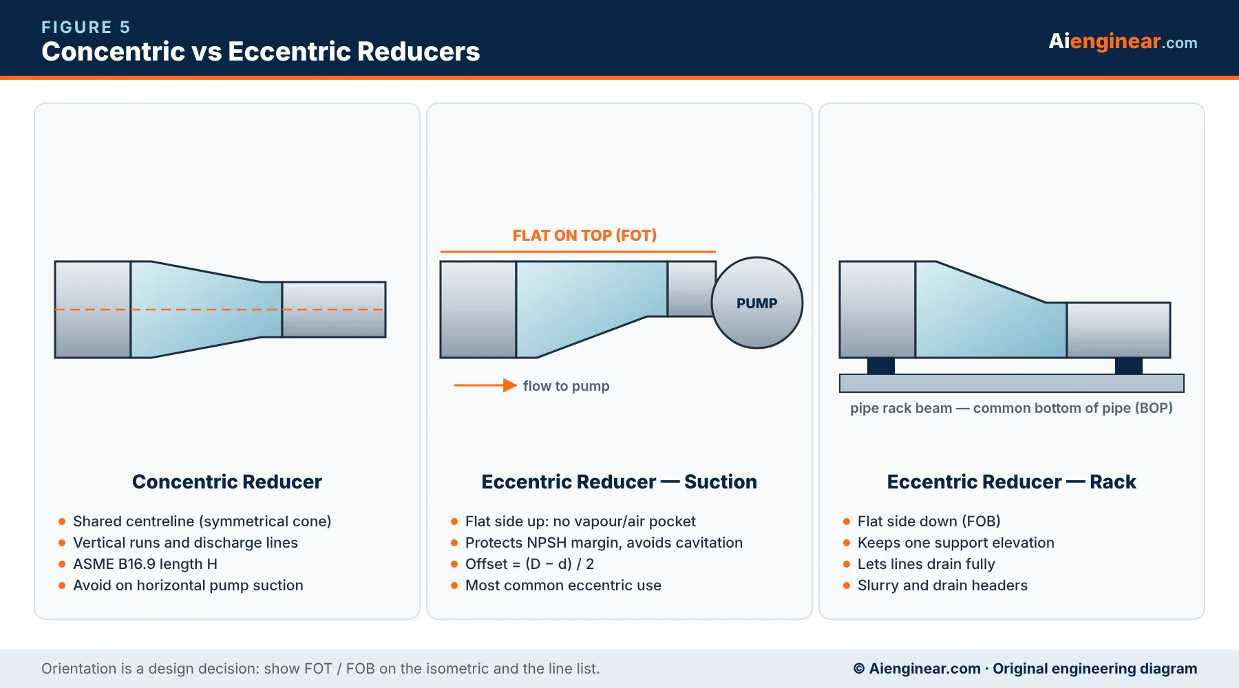
Eccentric reducer orientation: flat on top or flat on bottom?
- Flat on top (FOT) on horizontal pump suction lines. This stops vapour or air collecting at the top of the reducer, which would starve the pump and reduce NPSH margin.
- Flat on bottom (FOB) on pipe racks so the line keeps one bottom-of-pipe elevation for supports, and on lines that must drain fully.
- Concentric on vertical lines, pump and compressor discharge, and most general piping.
Eccentric reducers also need orientation shown on the isometric, otherwise they are sometimes installed upside down. Small-bore size changes use swage nipples (MSS SP-95-2024), which come concentric or eccentric with plain, bevelled or threaded ends — for example PBE × TSE (plain both ends × threaded small end).
Aienginear · Table 7
Concentric vs eccentric reducer
Orientation and use cases
| Feature | Concentric | Eccentric |
|---|---|---|
| Centreline | Common | Offset by (D − d)/2 |
| Horizontal pump suction | Not recommended | Preferred, flat on top |
| Vertical lines | Preferred | Rarely needed |
| Pipe rack (common BOP) | Bottom elevation changes | Flat on bottom keeps elevation |
| Drainage of horizontal line | Can trap liquid | Flat on bottom drains fully |
| Dimension standard | ASME B16.9 (length H) | ASME B16.9 (length H) |
Pipe caps, plugs and bull plugs
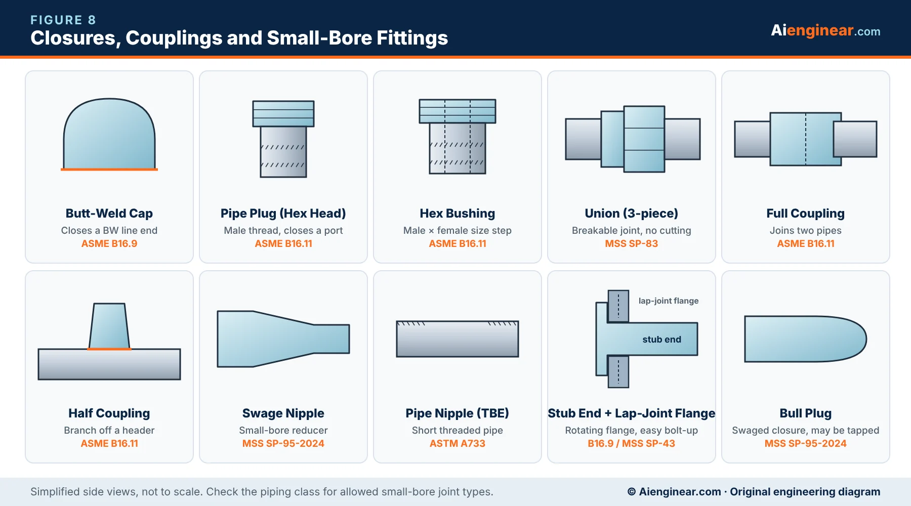
Caps close the end of a butt-weld line and are used for dead ends, future tie-ins and the ends of headers. A cap is a pressure part: the wall must match the pipe. Plugs (hex-head, square-head or round-head) are male-threaded closures for threaded ports such as drains, vents and gauge points; ASME B16.11 covers them. A bull plug is a swaged closure with a rounded end, sometimes tapped for a gauge or vent, made to MSS SP-95.
Field tip
Plastic thread protectors and end caps are shipping protection only. They must never be left in place as pressure closures, and they should be counted off at mechanical completion.
Couplings, unions, nipples and bushings
- Full coupling — joins two small-bore pipes of the same size, socket-weld or threaded (ASME B16.11).
- Half coupling — socket or thread on one end only; welded onto a header or vessel for a small branch, vent, drain or instrument connection.
- Reducing coupling — joins two different small-bore sizes on a common centreline.
- Union — three parts (two ends and a nut) that let a joint be broken without cutting the pipe. Used next to instruments, small pumps and items that need regular removal; steel unions follow MSS SP-83.
- Pipe nipple — a short length of pipe, threaded both ends (TBE), one end (TOE), or plain. Close nipples are fully threaded. ASTM A733 covers welded and seamless steel nipples.
- Bushing — a male × female threaded reducer, usually hex-headed. Many piping classes prohibit bushings in hydrocarbon service because the thin section can crack; a swage nipple is then used instead.
Stub ends
A stub end is a short butt-weld fitting with a lap on one end. A loose lap-joint flange slides over it, so the expensive alloy (for example stainless or nickel alloy) only has to be used for the stub, while the flange can be carbon steel. The flange also rotates, which makes bolt-hole alignment easy.
- Long-pattern stub ends — dimensions in ASME B16.9.
- Short-pattern stub ends — MSS SP-43, common with light-wall stainless pipe.
- Types A, B and C — Type A suits a standard lap-joint flange with a radiused bore; Type B is used with a slip-on flange as the backing flange; Type C is a fabricated or plain-lap design. Confirm the type with the flange you buy.
Olets (integrally reinforced branch outlets)
An olet is a forged fitting welded onto a run pipe to make a branch, with the reinforcement built into the body. Most are made to MSS SP-97. Names such as Weldolet, Sockolet and Threadolet are trade names that the industry uses generically; specifications often call them butt-weld, socket-weld and threaded outlets.
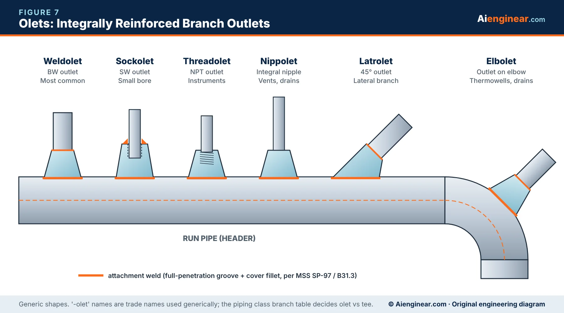
Aienginear · Table 8
Olet selection guide
Match the outlet to the branch end and location
| Olet | Branch end | Typical branch size | Typical use |
|---|---|---|---|
| Weldolet (butt-weld outlet) | Bevelled for butt weld | Small bore to large; most often below ½ run | Process branches in BW piping |
| Sockolet (socket-weld outlet) | Socket weld | NPS ⅛–4 (usually ≤ 2) | Small-bore branches, vents, drains |
| Threadolet (threaded outlet) | NPT female | NPS ⅛–4 | Instruments and utilities where threads are allowed |
| Nippolet | Integral nipple, plain or threaded | NPS ½–2 | Valved vents and drains |
| Latrolet | 45° outlet (BW, SW or THD) | Small to medium | Lateral branches, sample points |
| Elbolet | Outlet on an elbow (BW, SW or THD) | Small | Thermowells and drains at elbows |
| Sweepolet-type contoured outlet | Butt weld, integral sweep | Medium to large | High-pressure or cyclic service needing low stress |
Tee or olet?
Most piping classes include a branch table that tells you whether to use a tee, a reducing tee, an olet or a half coupling for each run × branch combination. Where the class has no table, the branch must be checked with the ASME B31.3 304.3 area-replacement rules.
Socket-weld and threaded fittings (ASME B16.11)
Forged socket-weld and threaded fittings cover NPS ⅛–4. Their class number is not a pressure in psi; it tells you which pipe schedule the fitting is meant to match.
Aienginear · Table 9
ASME B16.11 class vs pipe schedule
Use the class that matches the pipe wall in the piping class
| Fitting class | End type | Matching pipe wall | Typical use |
|---|---|---|---|
| 2000 | Threaded only | Sch 80 / XS | Low-pressure threaded utilities |
| 3000 | Threaded | Sch 160 | General threaded service |
| 3000 | Socket weld | Sch 80 / XS | Most common small-bore process class |
| 6000 | Threaded | XXS | High-pressure threaded |
| 6000 | Socket weld | Sch 160 | High-pressure small bore |
| 9000 | Socket weld only | XXS | Very high pressure, NPS ½–2 |
Fitting pressure rating is the rating of the matching pipe calculated to the design code. Threaded joints lose wall to thread depth, which is why the threaded class is one step higher for the same pipe.
- Socket-weld fittings: 45° and 90° elbows, tees, crosses, full, half and reducing couplings, caps, unions and inserts. Good strength and no thread leak path, but the internal crevice can trap corrosive fluids, so many classes ban SW in, for example, wet chlorides, caustic or food service.
- Threaded fittings: the same shapes plus plugs, bushings and street elbows. Quick to install but threads leak more often and loosen under vibration. ASME B31.3 limits threaded joints where crevice corrosion, severe erosion or cyclic loading may occur. Where threads are kept in hydrocarbon service, the class may require seal welding.
B16.9 dimension and K-factor finder
Pick a size to see the main ASME B16.9 centre-to-end dimensions and an indicative resistance coefficient (K) for each fitting. Use it for early layout and hydraulics; use the purchased standard and vendor drawings for construction.
Inch values from the ASME B16.9 tables; mm are converted and rounded, so the metric tables of the edition you purchase govern. K = n × fT (Crane TP-410), fully turbulent flow, indicative only. “—” means not standardised at that size.
How to select a pipe fitting: step by step
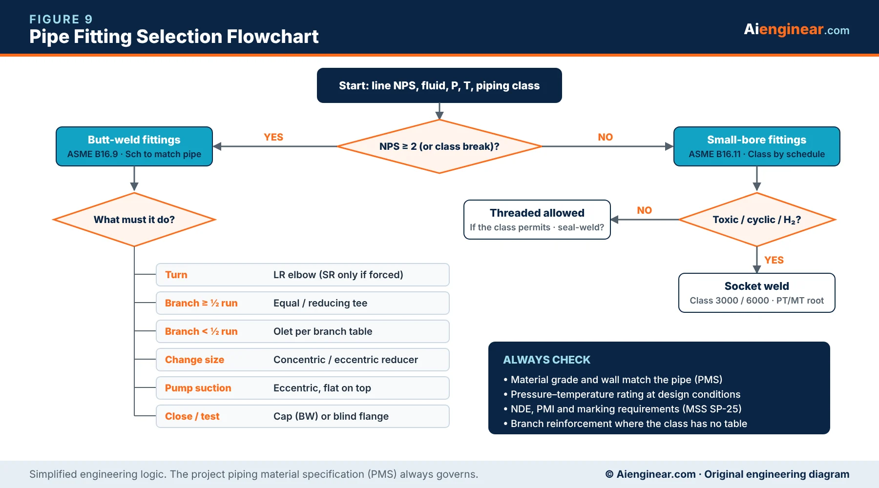
- 1. Start from the piping class (PMS). It fixes material, wall, end connection and branch table for each line.
- 2. Confirm size and wall. Order butt-weld fittings with the same schedule as the pipe, or a specified wall in mm for non-standard pipe.
- 3. Pick the shape that does the job with the fewest joints. An LR elbow beats two 45° elbows; a reducing elbow saves a weld.
- 4. Check orientation. Eccentric reducers FOT on pump suction; FOB on racks.
- 5. Check hydraulics. Use the K values above in your pressure-drop check, especially on pump suction and two-phase lines.
- 6. Check special service. Low temperature needs impact-tested grades; sour service needs hardness limits (NACE MR0175/ISO 15156 or MR0103); hydrogen and cyclic service usually ban threads.
- 7. Write a complete description. Example: Elbow 90° LR, NPS 6, Sch 40, BW, ASTM A234 WPB, ASME B16.9-2024, seamless.
Aienginear · Table 10
Quick selection guide
The usual first choice for each requirement
| Requirement | Recommended fitting | Why |
|---|---|---|
| Change direction | 90° or 45° LR elbow | Lower loss than SR |
| Very tight space | SR elbow (check rating) | Shorter centre-to-end |
| Piggable line | 3D–5D bend, barred tee | Pig passes freely |
| Full-size or large branch | Equal or reducing tee | Integral reinforcement |
| Small branch on large header | Weldolet / sockolet | Cheaper and lighter than a tee |
| Size change, vertical | Concentric reducer | Symmetric flow |
| Size change, pump suction | Eccentric reducer, FOT | No vapour pocket |
| Small-bore size change | Swage nipple | Avoids bushings |
| Dead end / future tie-in | BW cap | Full-strength closure |
| Joint that must be broken | Union or flange | No cutting |
| Alloy line, carbon steel flanges | Stub end + lap-joint flange | Saves alloy cost |
| Instrument tap | Half coupling or threadolet | Simple, standard |
Common pipe fitting mistakes to avoid
- Using an SR elbow without checking its pressure rating against the line.
- Ordering a fitting by “class” (for example Class 300) when it is a B16.9 butt-weld fitting — it must be ordered by schedule.
- Fitting wall thinner than the pipe (or much thicker without a taper), causing mismatch at the weld.
- Installing an eccentric reducer upside down on a pump suction.
- Leaving out the 1.6 mm socket-weld gap, or using socket welds in crevice-corrosive service.
- Using threaded joints or bushings in vibrating, cyclic or hydrocarbon lines where the class bans them.
- Welding an olet onto a run pipe without a proper bore-out, leaving weld spatter and coupons inside.
- Mixing up stub-end types with the wrong backing flange.
- Citing withdrawn ASME B16.28 on new specifications instead of B16.9.
Inspection, testing and marking
At receipt, check the marking (manufacturer, grade, size, schedule, standard and heat number), the material test report against the purchase order, bevel geometry, wall thickness at the weld end and the inside surface for laps and cracks. Alloy fittings normally get positive material identification (PMI). Our full pipe fittings inspection guide covers visual, dimensional, NDT and proof-test checks, and the piping interview questions page is a good revision list.
Key takeaways
- Butt-weld fittings (ASME B16.9-2024) are ordered by size, schedule and grade — they have no pressure class.
- Forged small-bore fittings (ASME B16.11-2021) use Classes 2000–9000, which match pipe schedules.
- LR elbows (1.5 × NPS) are the default; SR elbows only where space forces them.
- Eccentric reducers go flat on top on pump suction and flat on bottom on racks.
- The branch table in the piping class decides between a tee and an olet.
Frequently asked questions about pipe fittings
What are the main types of pipe fittings?
The main types are elbows and bends, tees, crosses and laterals, reducers and swages, caps and plugs, couplings, unions and nipples, stub ends, and olets (branch outlets). Each changes direction, branches, changes size, closes, or joins the pipe.
What is the difference between a long-radius and a short-radius elbow?
A long-radius elbow has a centreline radius of 1.5 × NPS and a short-radius elbow 1.0 × NPS. LR elbows have lower pressure drop and erosion and are the default in process piping; SR elbows save space but may have a lower pressure rating.
Which standard covers butt-weld pipe fittings?
ASME B16.9 (current edition 2024) covers factory-made wrought butt-welding fittings from NPS ½ to 48, including elbows, returns, tees, crosses, reducers, caps and long-pattern stub ends. Material grades come from ASTM A234, A403, A420, A815 and similar.
Is ASME B16.28 still valid?
No. ASME B16.28 for short-radius elbows and returns was withdrawn and its content was moved into ASME B16.9. New specifications should cite B16.9.
What do Class 3000 and Class 6000 mean for forged fittings?
They are ASME B16.11 designations linked to pipe wall. A Class 3000 socket-weld fitting matches Sch 80 pipe and a Class 6000 socket-weld fitting matches Sch 160. The number is not a pressure in psi.
Why is an eccentric reducer installed flat side up on pump suction?
Flat on top prevents vapour or air from collecting at the top of the reducer. A trapped pocket can reduce NPSH margin, cause cavitation and damage the pump.
When should I use an olet instead of a tee?
Use an olet when the branch is small compared with the run — typically less than about half the run size — and the piping class branch table calls for it. Tees are used for full-size and large branches.
What is the gap in a socket-weld joint?
About 1.6 mm (1/16 in) between the pipe end and the socket shoulder before welding. It allows thermal expansion during welding and prevents cracking of the fillet weld.
Test your knowledge: pipe fittings quiz
1. What is the centreline radius of a long-radius elbow (NPS ¾ and larger)?
LR elbows are 1.5 × NPS; SR elbows are 1.0 × NPS.
2. Which standard now covers short-radius elbows and returns?
B16.28 was withdrawn; its content is in B16.9.
3. How should an eccentric reducer be installed on a horizontal pump suction?
Flat on top stops a vapour/air pocket forming ahead of the pump.
4. A Class 3000 socket-weld fitting is intended for pipe of which wall?
SW Class 3000 ↔ Sch 80, 6000 ↔ Sch 160, 9000 ↔ XXS.
5. How are B16.9 butt-weld fittings pressure-rated?
They are designed to equal the matching seamless pipe.
6. Which fitting keeps pigs from entering a branch?
Guide bars across the branch keep the pig in the run.
7. What gap is left at the bottom of a socket before welding?
The gap allows expansion and prevents fillet weld cracking.
8. Which olet is designed for a branch on an elbow?
Elbolets are contoured to sit on an elbow, often for thermowells.
9. Why use a stub end with a lap-joint flange on a stainless line?
The loose carbon steel flange saves alloy and eases alignment.
10. Which standard covers integrally reinforced branch outlets?
MSS SP-97 covers weld, socket and threaded outlets.
References
- ASME B16.9-2024, Factory-Made Wrought Buttwelding Fittings.
- ASME B16.11-2021, Forged Fittings, Socket-Welding and Threaded.
- ASME B16.5-2025, Pipe Flanges and Flanged Fittings: NPS ½ Through NPS 24.
- ASME B31.3-2024, Process Piping.
- ASME B16.25, Buttwelding Ends; ASME B16.49, Factory-Made Wrought Steel Buttwelding Induction Bends.
- MSS SP-97-2019, MSS SP-95-2024, MSS SP-75-2025, MSS SP-83, MSS SP-43, MSS SP-25.
- ASTM A234/A234M, A403/A403M, A420/A420M, A815/A815M, A960/A960M, A105/A105M, A182/A182M.
- Crane Co., Technical Paper No. 410, Flow of Fluids Through Valves, Fittings and Pipe (K = n·fT method).

Written by Muhammad Raza
Founder of Aienginear. Engineering and digital solutions professional with 26+ years managing projects, plant shutdowns and turnarounds in oil & gas, petrochemical and power generation.