
AIENGINEAR · PIPING QA/QC
A fitting that leaves the stockyard with the wrong grade, a hidden lap or a heat number nobody can trace becomes a plant problem the day it is welded in. This guide converts the governing standards into a sequence an inspector can actually follow, at the supplier’s works or at site receiving: what to check, which test belongs to which fitting, how to measure it, and what to do when something fails. It also includes a free acceptance calculator and a printable checklist.
What is pipe fittings inspection?
Pipe fittings inspection is the documented check that each elbow, tee, reducer, cap, stub end or forged fitting is the ordered material and size, is free of unacceptable surface flaws, is within the dimensional tolerances of its standard (such as ASME B16.9 or B16.11), carries the test evidence its material specification and purchase order require, and is marked so it can be traced to its mill test certificate.
Individual wrought fittings are not routinely hydrotested: ASME B16.9 and ASTM A960 only require them to be capable of the test pressure of matching seamless pipe. Fitting design strength is proven once by the manufacturer, usually by a proof test; the installed piping is then pressure tested under the piping code.
1. What does pipe fitting inspection cover?
Inspection applies to three product families: butt-welding fittings (long- and short-radius elbows, 180° returns, equal and reducing tees, crosses, concentric and eccentric reducers, caps and lap-joint stub ends), forged socket-weld and threaded fittings (couplings, half-couplings, elbows, tees, crosses, caps, plugs, bushings and unions) and branch outlet fittings. Each family has its own dimensional standard, but the inspection logic is the same.
Every fitting must pass four questions, asked in this order because a failure at an early step makes the later ones pointless:
- Right item? Specification, grade, construction class, size, wall or pressure class and end preparation agree with the purchase order (PO) and the certificate.
- Traceable? The heat or lot number on the fitting appears on the mill test certificate (MTC), normally EN 10204 type 3.1, or 3.2 where an independent inspector must countersign.
- Sound? No cracks, laps, gouges or other imperfections beyond what the specification permits, and every required NDT has been performed and accepted.
- Within tolerance? Diameters, wall thickness, centre-to-end dimensions and angularity are inside the dimensional standard.
New to the product families? Start with our overview of types of pipe fittings and the pipe fittings manufacturing process. The manufacturing route (hot-formed seamless, welded from plate or pipe, or forged) decides which defects are likely and which tests are mandatory.
2. Governing standards and their current editions
No single document covers a fitting. Three layers act together: a dimensional standard (shape, tolerances, design qualification, marking), a material specification (chemistry, heat treatment, mechanical tests and NDT by class) and the project documents (PO, datasheet, inspection and test plan (ITP) and supplementary requirements). The table lists editions current on the review date; always inspect to the edition named in your contract.
Aienginear · Table 1
Standards that govern pipe fitting inspection
Editions verified 15 October 2026 against publisher listings
| Document | Current edition | What it controls | Inspector’s note |
|---|---|---|---|
| ASME B16.9 | 2024 | Factory-made wrought butt-welding fittings, NPS ½–48: dimensions, tolerances, design qualification, marking | Sets no chemistry or mechanical properties; those come from the ASTM specification |
| ASME B16.11 | 2021 | Forged fittings: threaded Class 2000/3000/6000; socket-weld Class 3000/6000/9000 | Pressure class is matched to pipe schedule; check the class on the marking |
| ASME B16.25 | 2022 | Butt-welding end preparation (bevel geometry) | Bevel angle, root face and compound bevels for heavy walls |
| ASTM A234/A234M | A234/A234M-26 | Wrought carbon and alloy steel fittings for moderate and high temperature (WPB, WPC, WP11, WP22, WP91 …) | Grade-specific heat treatment and hardness limits |
| ASTM A403/A403M | A403/A403M-26a | Wrought austenitic stainless fittings (WP304, WP316L …) in classes S, W, WX, WU and CR | Class decides weld NDT |
| ASTM A420/A420M | A420/A420M-26 | Carbon and alloy steel fittings for low-temperature service (WPL6, WPL3, WPL8 …) | Charpy impact testing is mandatory |
| ASTM A960/A960M | A960/A960M-25a | Common requirements for wrought fittings: surface quality, repair, hydrotest capability, supplementary requirements | Many product-spec clauses say “see A960”; read both together |
| ASTM A105 / A182 | A105/A105M-26; A182 current | Forgings for B16.11 fittings | Our ASTM A105 guide |
| MSS SP-43 | Current edition | Light-wall corrosion-resistant butt-welding fittings (Sch 5S/10S) | Marked “CR”; class requires no weld radiography |
| MSS SP-25 | 2023 | Standard marking system for valves, fittings, flanges and unions | PO and product spec may add marks |
| ASME BPVC Section V | 2025 | NDT methods: Art. 2 RT, Art. 4/5 UT, Art. 6 PT, Art. 7 MT, Art. 9 VT, Art. 23 ASTM practices | Technique and procedure requirements referenced by the codes |
| ASME B31.3 | 2024 | Process piping: examination of installed welds, system leak test | A system test is not a fitting test |
| API RP 578 | 4th edition (2023) | Material verification programme (PMI) for alloy piping | Defines PMI scope, methods and records |
| NACE MR0175 / ISO 15156; NACE MR0103 / ISO 17945 | Current editions | Materials for wet H₂S (sour) service in production and refining | Hardness limits and HIC/SSC qualification |
Editions from ASME, ASTM, ANSI, MSS and API publisher listings, checked 15 October 2026. “Current edition” means confirm the year on the publisher’s site before quoting it in an ITP.
3. Which tests apply to which fitting?
Most inspection guides give one long list of tests. In practice the list depends on construction, material and service. Use this matrix to build or check an ITP, then confirm each cell against the edition on your order.
Aienginear · Table 2
Test selection matrix by fitting type
Required = by the product specification · PO = only if ordered (class, supplementary requirement or purchase order) · — = not normally applicable
| Test / check | CS seamless A234 WPB | CS welded A234 WPB-W | Stainless A403 WP-S / W / WX / WU | Stainless light-wall A403 CR (SP-43) | Low-temp A420 WPL6 | Forged B16.11 A105 / A182 |
|---|---|---|---|---|---|---|
| Visual + dimensional | Required | Required | Required | Required | Required | Required |
| Heat chemical analysis | Required | Required | Required | Required | Required | Required |
| Tensile test | Required | Required | Required | Required | Required | Required |
| Hardness | Required (max) | Required (max) | Class / PO | Class / PO | Class / PO | Required (A105) |
| Charpy impact | PO | PO | PO (cryogenic) | PO | Required | PO / use A350 for low temp |
| RT / UT of welds | — | Required for maker’s filler-metal welds | By class: W, WX (RT); WU (UT) | Not required by class | Construction / PO | — |
| MT / PT | PO / supplementary | PO / supplementary | PT if ordered | PT if ordered | PO | PO |
| Hydrostatic test of the fitting | Only if PO | Only if PO | Only if PO | Only if PO | Only if PO | Only if PO |
| Design qualification (proof test or analysis) | Maker’s qualification | Maker’s qualification | Maker’s qualification | Per SP-43 | Maker’s qualification | Per B16.11 basis |
| IGC (ASTM A262) | — | — | PO / supplementary | PO | — | A182 SS: PO |
| HIC / SSC, sour hardness | Sour service PO | Sour service PO | Sour service PO | — | Sour service PO | Sour service PO |
| PMI | Usually — | Usually — | PO / API RP 578 | PO | PO | Alloy grades: PO |
“Required (max)” means the specification sets a maximum hardness; the number of fittings tested follows the specification’s lot rules. A planning aid, not a substitute for the specification.
4. Inspection workflow and hold points
Run the checks in the order that stops bad material earliest. Paperwork comes first, because a fitting that cannot be traced is rejected however good it looks.
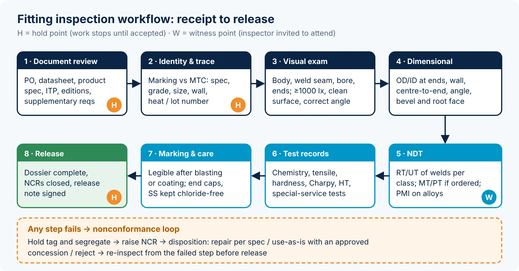
- Document review (hold): PO, datasheet, product and dimensional standards with editions, ITP and every supplementary requirement (A960 S-numbers, sour-service, impact or PMI clauses).
- Identity and traceability (hold): compare each marking with the MTC: specification, grade, construction suffix, size, wall and heat number. Check that MTC values are inside the specification limits, not merely that values are printed.
- Visual examination: body, weld seam, bore and ends under adequate light.
- Dimensional check: to the sample size in the ITP, with calibrated instruments.
- NDT (witness): review or witness RT, UT, MT, PT and PMI as required; check technique, coverage, operator certification and acceptance criteria.
- Test records: mechanical results, heat-treatment charts, impact and special-service tests.
- Marking and preservation: marks legible after blasting or coating, bevels protected, stainless kept away from carbon-steel tools and chlorides.
- Release (hold): dossier complete, all NCRs closed, release note signed.
Sampling: marking, MTC review and visual examination are normally 100 %. Dimensional and NDT sampling should be written into the ITP; where a statistical plan is agreed, ISO 2859-1 or ANSI/ASQ Z1.4 attribute plans are the usual basis. Any rejected sample widens the check to the whole lot.
5. Visual examination of pipe fittings
Visual testing (VT) is the cheapest method and catches most forming and handling damage. For direct visual examination, ASME Section V Article 9 calls for the eye within about 600 mm (24 in) of the surface, a viewing angle of at least 30° to the surface and at least 1000 lux (100 fc) on the area examined. Remove scale, oil and loose paint first; a varnish or temporary coating can hide a lap.
Where to look
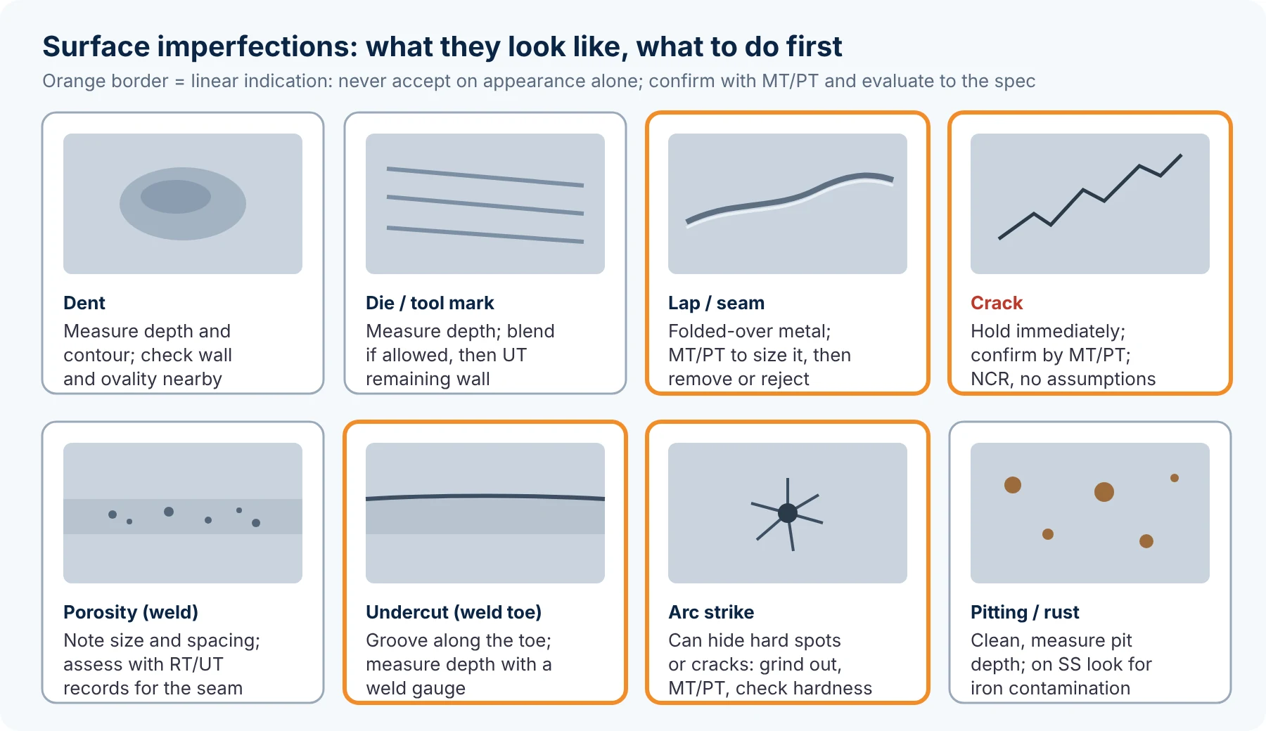
- Outer body: dents, gouges, die and tool marks, laps, seams, cracks, arc strikes.
- Elbow intrados and extrados: wrinkles or buckling on the inside radius; thinning and surface checking on the outside radius, which is stretched during forming.
- Tee crotch and branch: the most heavily worked zone of an extruded tee; look closely for cracks and laps.
- Weld seams (welded fittings): undercut, porosity, underfill, excess reinforcement, spatter and repair grinding.
- Bore: scale, internal weld protrusion, foreign material.
- Ends: bevel damage, laminations visible on the bevel face, burrs.
How to disposition a surface imperfection
ASTM A960 holds the surface-quality rules that A234, A403 and A420 refer to. In outline: an imperfection may be removed by grinding provided the remaining wall is not below the required minimum; a deeper defect may be weld-repaired only where the specification allows it, with a qualified procedure and welder, and the repaired area must be re-examined (and re-heat-treated where the grade requires). Use the depth limits in the edition you work to; never borrow a number from another product standard.
Rule that never changes: any linear indication (crack, lap, seam) is confirmed with MT on carbon and low-alloy steel, or PT on austenitic stainless, then sized and dispositioned. A crack is never accepted on appearance, whatever its length.
6. Dimensional inspection and ASME B16.9 tolerances
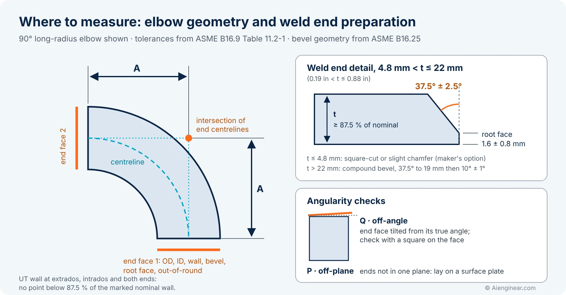
Dimensional checks prove that the fitting will fit up to the pipe and the rest of the line. For butt-welding fittings, measure at each welding end and on the overall geometry.
Aienginear · Table 3
ASME B16.9 tolerances for butt-welding fittings
Inches, ± unless noted · from B16.9 Table 11.2-1 (2024 numbering) · multiply by 25.4 for mm
| NPS | OD at bevel | ID at end | Centre-to-end A, B, C, M | Off-angle Q | Off-plane P |
|---|---|---|---|---|---|
| ½ – 2½ | +0.06 / −0.03 | 0.03 | 0.06 | 0.03 | 0.06 |
| 3 – 3½ | 0.06 | 0.06 | 0.06 | 0.03 | 0.06 |
| 4 | 0.06 | 0.06 | 0.06 | 0.03 | 0.06 |
| 5 – 8 | +0.09 / −0.06 | 0.06 | 0.06 | 0.06 | 0.12 |
| 10 – 12 | +0.16 / −0.12 | 0.12 | 0.09 | 0.09 | 0.19 |
| 14 – 16 | +0.16 / −0.12 | 0.12 | 0.09 | 0.09 | 0.25 |
| 18 | +0.16 / −0.12 | 0.12 | 0.09 | 0.12 | 0.38 |
| 20 – 24 | +0.25 / −0.19 | 0.19 | 0.09 | 0.12 | 0.38 |
| 26 – 30 | +0.25 / −0.19 | 0.19 | 0.12 | 0.19 | 0.38 |
| 32 – 48 | +0.25 / −0.19 | 0.19 | 0.19 | 0.19 | 0.50 (NPS 32–42) / 0.75 (NPS 44–48) |
Wall thickness: no point thinner than 87.5 % of the marked nominal wall unless the purchaser specifies otherwise. Out-of-round at the ends is the sum of the absolute plus and minus OD tolerances. 180° returns, reducer lengths and cap heights have their own rows in B16.9. SI tables in B16.9 carry their own rounded values; confirm the NPS 32–48 angularity values against your controlled copy.
Measuring practice
- Wall thickness: UT thickness gauge, calibrated on a step block of the same material, at the extrados and intrados of elbows, the crotch of tees and both ends of reducers. Compare with 87.5 % of the nominal wall of the schedule marked on the fitting; nominal values are in our pipe sizes and schedule chart.
- OD and ovality: circumference tape or calipers in two planes 90° apart.
- Bevel (ASME B16.25): bevel protractor and weld gauge. For walls over 4.8 mm up to 22 mm (0.19–0.88 in): 37.5° ± 2.5° with a 1.6 ± 0.8 mm root face. Thinner walls may be square-cut or slightly chamfered; walls over 22 mm take the compound bevel (37.5° to a height of 19 mm, then 10° ± 1°). The PO may specify a different preparation.
- Angularity: a square against the end face for off-angle; the fitting set on a surface plate for off-plane.
- Forged B16.11 fittings: socket bore diameter and depth, wall at socket and body, centre-to-bottom of socket, and thread gauging with NPT plug and ring gauges.
Full dimension tables are in pipe fittings dimensions and materials.
7. Free fitting acceptance calculator
Pick the size, enter your nominal and measured values, and the calculator returns the B16.9 tolerance band, the 87.5 % minimum wall with an accept/reject flag, and the minimum proof test pressure. It runs in your browser; nothing is stored.
Aienginear · Calculator
B16.9 fitting acceptance and proof-pressure calculator
Tolerances from ASME B16.9 · wall rule 87.5 % of nominal · P = 2Stf/D
This calculator needs JavaScript. The same values are in Table 3 and Section 9.
Proof test pressure (manufacturer’s design qualification)
Planning aid only. Accept or reject against the controlled copy of the edition on your PO. f = 1.00 applies when three or more specimens are tested; use the factor from Table 9.3.1-1 for fewer tests.
8. Nondestructive testing (NDT) of pipe fittings
Choose NDT by the flaw you need to find, then by what the material allows. The product specification and fitting class set what is mandatory; the PO can add more.
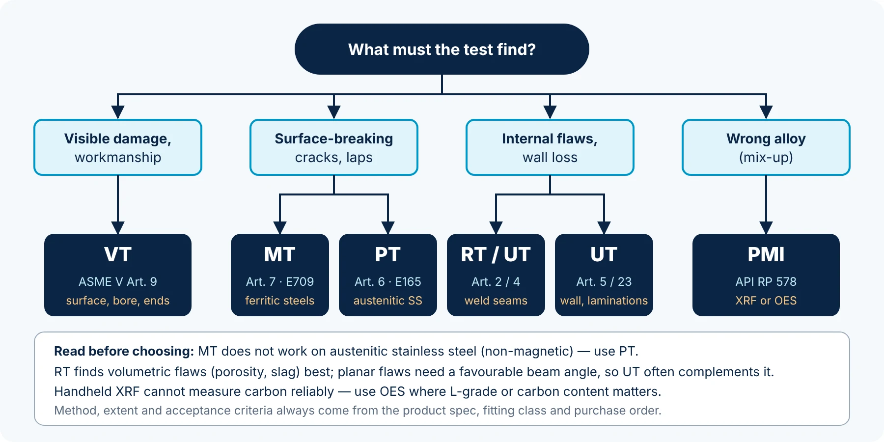
Aienginear · Table 4
NDT methods for pipe fittings
Technique references: ASME BPVC Section V (2025) and ASTM practices
| Method | Finds | Best used on | Limits to remember | Typical references |
|---|---|---|---|---|
| VT – visual | Surface damage, workmanship, weld profile | All fittings, 100 % | Only what the eye can reach; needs light and a clean surface | ASME V Art. 9 |
| PT – liquid penetrant | Open surface cracks, laps, porosity | Stainless, nickel alloys, any non-porous metal | Flaw must be open to the surface; dwell and development times matter; use low-halogen, low-sulfur consumables on stainless and nickel alloys | ASME V Art. 6; ASTM E165/E165M, E1417 |
| MT – magnetic particle | Surface and slightly sub-surface linear flaws | Carbon and low-alloy (ferromagnetic) steel | Not for austenitic stainless; magnetise in two directions; demagnetise if required | ASME V Art. 7; ASTM E709 |
| UT – ultrasonic | Internal weld flaws, laminations, wall thickness | Weld seams (WU class), plate, thickness surveys | Curvature and coarse austenitic weld grain reduce reliability; procedure must suit geometry | ASME V Art. 4, 5 and 23 |
| RT – radiography (film or digital) | Porosity, slag, lack of fusion and penetration in welds | Weld seams (W and WX classes) | Planar flaws parallel to the beam can be missed; radiation safety controls | ASME V Art. 2; ASME VIII-1 UW-51 acceptance for WX |
| PMI – positive material identification | Alloy mix-up | Alloy steel, stainless, nickel alloys | Handheld XRF does not measure carbon reliably; use OES for L-grades and carbon checks | API RP 578; MSS SP-137 |
Acceptance criteria come from the product specification, fitting class and PO, not from the NDT technique standard.
Personnel: NDT operators should be qualified and certified to the scheme the contract names, usually ASNT SNT-TC-1A, ANSI/ASNT CP-189 or ISO 9712, normally Level II to perform and interpret. Ask for the certificate and the written procedure, not just the report.
9. Proof test vs hydrotest vs system pressure test
These three tests are often confused, which leads either to needless testing or to false confidence.
Aienginear · Table 5
Three different pressure tests
Who does it, why, and which document governs
| Test | Who / when | Purpose | Governing basis |
|---|---|---|---|
| Hydrostatic test of a fitting | Manufacturer, only if ordered | Leak and strength check of individual fittings | Not required by ASME B16.9 or ASTM A960; fittings must be capable of the test pressure required for matching seamless pipe |
| Design proof test | Manufacturer, once per design family | Proves the fitting design is at least as strong as the pipe it joins | ASME B16.9 §9 (B16.11 and MSS practices for their scopes); one of several design-qualification routes |
| System pressure / leak test | Constructor, after erection | Proves the installed piping (pipe, fittings, welds, flanges) is leak-tight | Piping code, e.g. ASME B31.3: hydrostatic at 1.5 × design pressure, adjusted for temperature |
How the ASME B16.9 proof test works
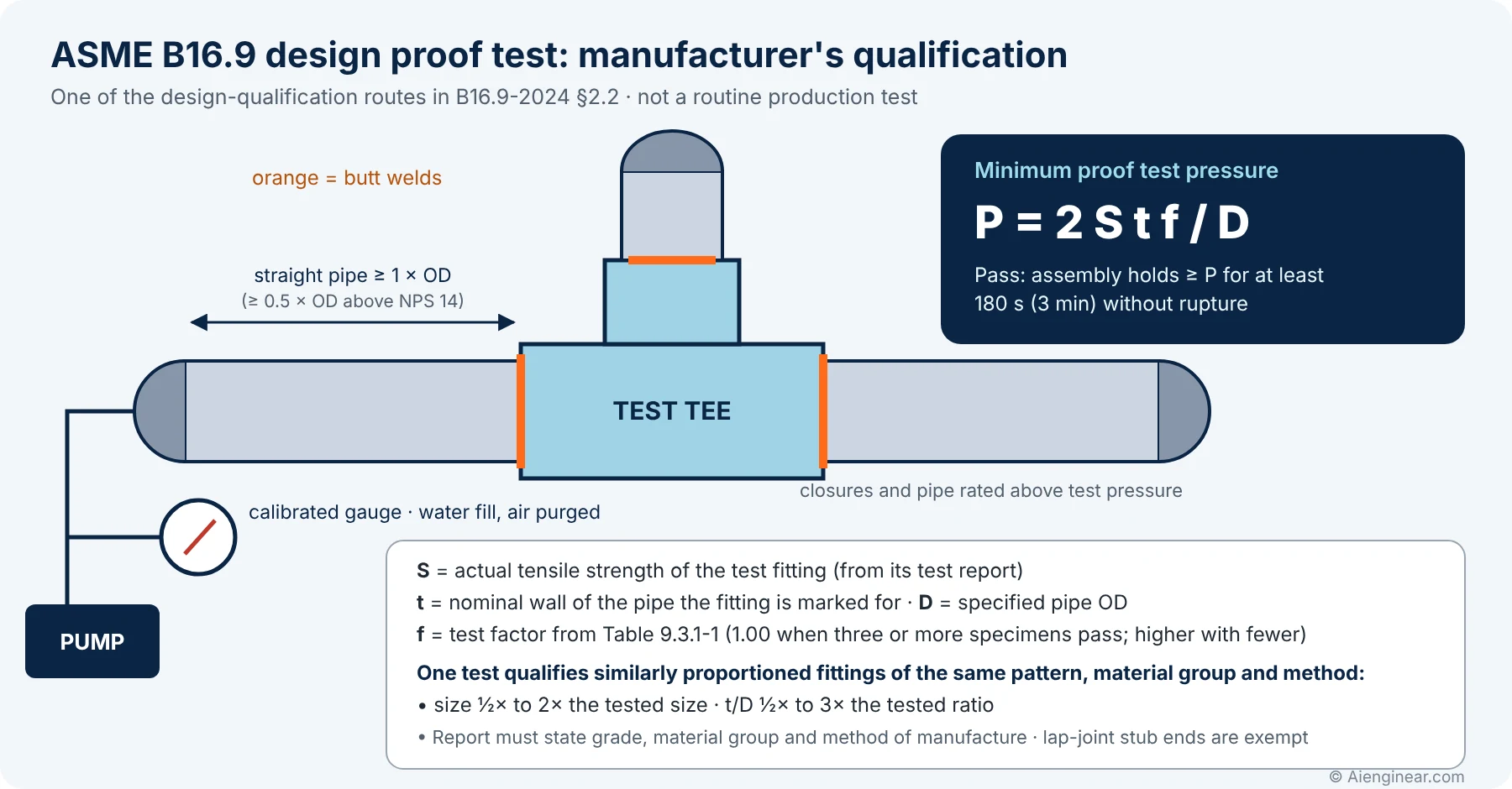
ASME B16.9-2024 lets a manufacturer establish a fitting design by code calculation (for example the ASME B31.3 rules for elbows and tees), by proof testing, or by experimental or validated finite-element stress analysis. Proof testing remains the common route. The test fitting is welded to straight pipe on every end (at least one pipe OD long up to NPS 14 and half an OD above), capped, filled with water with the air purged, and pressurised.
The minimum test pressure is P = 2 S t f / D, where S is the actual tensile strength of the test fitting, t the nominal wall of the pipe the fitting is marked for, D the specified pipe OD and f the test factor from B16.9 Table 9.3.1-1 (1.00 when three or more specimens are tested; higher when fewer are). The result is rounded to the nearest 0.2 MPa (25 psi). The assembly passes if it holds at least P for 180 s (3 min) without rupture. One successful qualification covers similarly proportioned fittings of the same pattern, material group and manufacturing method from half to twice the tested size and from half to three times the tested t/D ratio. Lap-joint stub ends are exempt because their rating comes from the flanged joint.
D = 168.3 mm · t = 7.11 mm · S (actual, from test report) = 492 MPa
P = 2 × 492 × 7.11 × 1.00 / 168.3 = 41.57 MPa → rounded 41.6 MPa (≈ 6,030 psi)
Pass: assembly holds ≥ 41.6 MPa for 3 min without rupture.
What the inspector checks: the proof test report exists; it covers the size, t/D ratio, pattern, material group and manufacturing method being supplied (B16.9-2024 requires the report to state grade, group and method); and the design has not changed since (dies, forming route, wall-thinning practice). A proof test never replaces production QC; every fitting still needs its material, dimensional and NDT checks.
System pressure testing after installation
Under ASME B31.3 the hydrostatic leak test pressure is at least 1.5 × design pressure, multiplied by the ratio of allowable stress at test temperature to allowable stress at design temperature (ratio capped at 6.5). A pneumatic test is normally 1.1 × design pressure and needs a separate risk assessment because of stored energy. Work out both with the Aienginear hydrotest pressure calculator.
Safety: every pressure test needs a written procedure, calibrated gauges (range ideally about twice the test pressure), air venting, exclusion zones out of the line of fire, controlled pressurisation and safe depressurisation. Never hammer or tighten a pressurised joint.
10. Mechanical, chemical and metallurgical tests
Most of these tests are carried out by the manufacturer and reported on the MTC. The inspector’s task is to confirm that the right tests were done on the right heat, at the right frequency, and that results meet the limits.
Aienginear · Table 6
Destructive and laboratory tests
What each verifies and where the limits come from
| Test | Verifies | Method | Typical limits / notes |
|---|---|---|---|
| Heat chemical analysis | Grade chemistry; carbon equivalent where specified | Ladle analysis by the steelmaker | On the MTC; check every element the grade limits |
| Product (check) analysis | Chemistry of the finished fitting | Sample from the fitting; ASTM A751 | Product-analysis tolerances apply, not heat limits |
| Tensile | Yield, tensile strength, elongation | ASTM A370 | A234 WPB: 415–585 MPa tensile, 240 MPa min yield |
| Hardness | Heat treatment; sour-service limits | Brinell ASTM E10; portable UCI A1038 or Leeb A956 for screening | A234 WPB/WPC: 197 HBW max; Cr-Mo grades and WP91 have their own limits |
| Charpy V-notch | Toughness at low temperature | ASTM A370 / E23 | A420 WPL6 at −46 °C (−50 °F): 18 J (13 ft·lbf) average, 14 J (10 ft·lbf) single, full-size specimens |
| Macro examination | Weld fusion, penetration, profile | Etched cross-section | Weld procedure or first-article checks |
| Micro examination | Microstructure after heat treatment; sensitisation | Polished and etched specimen | Needs a defined acceptance basis in the PO |
| Grain size | Austenitic grain size where specified | ASTM E112 | H-grades and some high-temperature orders |
| Ferrite content | Delta ferrite in stainless weld metal | Ferritescope (FN, AWS A4.2 / ISO 8249) or point count ASTM E562 | Range from the PO; 3–10 FN is a common project choice |
Values shown are for orientation; accept against the edition named on the PO.
Material background: carbon steel piping materials, alloy steel in piping and stainless steels in process piping.
11. Sour-service tests, IGC and PMI
Special tests are not routine. They are triggered by the service (wet H₂S, chlorides, high temperature) and must be written into the PO with the test method and acceptance criteria.
Aienginear · Table 7
Service-specific tests
Specify the method and acceptance in the purchase order
| Test | When it is called for | Method | What to specify |
|---|---|---|---|
| Intergranular corrosion (IGC) | Austenitic stainless that may be sensitised by heat treatment or welding | ASTM A262, usually Practice E (copper–copper sulfate–sulfuric acid, then bend) | Practice, specimen condition (sensitised or as-supplied), acceptance (no fissures on bending) |
| HIC – hydrogen-induced cracking | Plate-made (welded) carbon steel fittings in wet sour service | NACE / AMPP TM0284 | Test solution and crack-ratio limits (CLR, CTR, CSR) from the project sour-service specification |
| SSC – sulfide stress cracking | Sour service where material or weld must be qualified | NACE / AMPP TM0177 | Method (A, B, C or D), stress level, environment |
| Sour-service hardness | Any sour-service order | NACE MR0175 / ISO 15156 or MR0103 / ISO 17945 | Carbon steel base metal ≤ 22 HRC; weld and HAZ limits per the standard, commonly ≤ 250 HV10 |
| PMI | Alloy steel, stainless and nickel alloys, especially in hazardous service | XRF (alloying elements) or OES (adds carbon) | Percentage to test (often 100 % for alloys), elements, reading tolerance |
A passed special test shows the sample met a defined test condition; it does not guarantee corrosion performance in every service. Tie the test basis to the real process conditions.
12. Marking and material traceability
Marking links the steel in your hand to the results on paper. ASME B16.9 requires the manufacturer’s name or trademark, material identification (with the “WP” prefix in the grade certifying conformance to the standard), wall-thickness identification and size. B16.11 forged fittings add the pressure class. Where a fitting is too small for full marking, marks may be omitted in the reverse of the order the standard lists them, but heat or lot traceability must be kept, by tag if necessary.
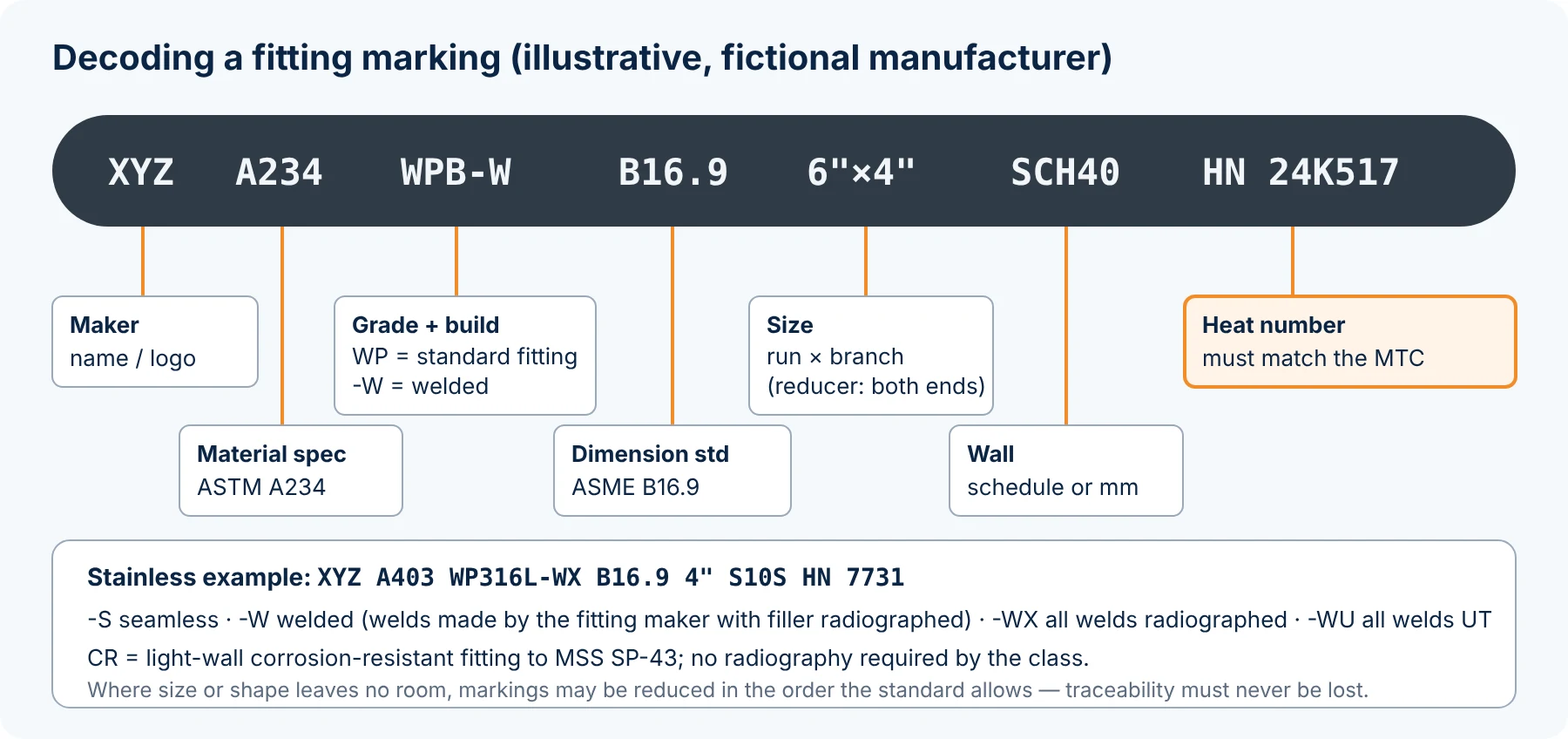
Aienginear · Table 8
Construction and class symbols you will see
Suffixes as defined in ASTM A403; carbon-steel specifications use similar logic
| Mark | Meaning | Weld NDT implied |
|---|---|---|
| WP | Fitting conforms to the dimensional standard (B16.9 / B16.11) as well as the ASTM specification | — |
| -S | Seamless construction | None (no weld) |
| -W | Welded construction | RT of welds made by the fitting maker with filler metal |
| -WX | Welded, all welds radiographed | 100 % RT, ASME VIII-1 UW-51 acceptance |
| -WU | Welded, all welds ultrasonically examined | 100 % UT in lieu of RT |
| CR | Light-wall corrosion-resistant fitting to MSS SP-43 | Not required by the class |
| S58 / special design | Fitting made to a special design rather than a standard table, supplied under A960 Supplementary Requirement S58 | As specified |
| Class 2000 / 3000 / 6000 / 9000 | B16.11 pressure class | — |
Confirm suffix meanings against the edition on your order.
If markings are lost through cutting, grinding or coating, put the fitting on hold. Restore identification only by a documented transfer witnessed by QC (with PMI for alloys); never re-stamp from memory. On thin-wall or low-temperature fittings, check that stamping uses low-stress (round-nosed) dies, or that vibro-etching or paint stencilling is used where the specification requires it.
13. Handling a nonconforming fitting
When any check fails, the response should be the same every time, so that nothing slips into the line by default:
- Tag and segregate the fitting (and its lot if the failure could be systemic).
- Raise an NCR with the requirement, the measured value, the evidence and the quantity affected.
- Disposition: repair in line with the specification; use-as-is only through a concession approved by the responsible engineer (and the client where the contract says so); or reject and return.
- Re-inspect from the failed step onward, including NDT after any repair.
- Close and trend: close the NCR before release and track repeat failures by supplier and defect type.
14. Printable receiving inspection checklist
Fill in the header, mark each row Accept, N/A or Hold, and record the evidence (MTC number, gauge serial, report number). Use Print / PDF for a branded sheet or CSV to keep the record in a spreadsheet.
Aienginear · Table 9 · Checklist
Pipe fitting receiving / final inspection checklist
17 checks · ASME B16.9 / B16.11 / B16.25 · ASTM A234, A403, A420, A960
| # | Check | Accept / N/A / Hold | Evidence / remarks |
|---|---|---|---|
| 1 | PO, datasheet, standards and editions, ITP and supplementary requirements reviewed | ||
| 2 | Fitting type, size, schedule or class, end preparation and quantity match the PO | ||
| 3 | MTC type (3.1 / 3.2) correct; chemistry and mechanical results within specification limits | ||
| 4 | Heat / lot number on each fitting matches the MTC | ||
| 5 | Heat-treatment condition and records as required by the grade | ||
| 6 | Visual: no cracks, laps or arc strikes; dents and marks within limits; bore clean | ||
| 7 | Wall thickness ≥ 87.5 % of nominal (or PO tolerance) at extrados, intrados, crotch and ends | ||
| 8 | OD/ID at ends, centre-to-end, off-angle and off-plane within B16.9 / B16.11 | ||
| 9 | Bevel angle and root face per B16.25 (or socket and thread gauging) acceptable | ||
| 10 | Weld NDT matches construction class (W / WX / WU); reports traceable | ||
| 11 | MT / PT / UT ordered by the PO done and accepted | ||
| 12 | Impact, hardness, IGC, HIC / SSC and PMI results as ordered | ||
| 13 | Design qualification (proof test or analysis) covers the size, t/D range, pattern and material group supplied | ||
| 14 | Marking complete and legible; matches PO and MTC | ||
| 15 | Bevel protection, end caps and rust preventive in place; stainless segregated from carbon steel | ||
| 16 | Repairs and concessions approved; all NCRs closed | ||
| 17 | Dossier complete; release note signed |
Without JavaScript, print the page (Ctrl + P) and tick by hand. Entries stay in your browser only.
15. Common inspection mistakes
- Treating the MTC as proof by its presence. Read the numbers: a printed tensile value below the minimum is still a rejection.
- Using MT on austenitic stainless. It will not magnetise; use PT.
- Accepting XRF PMI for an L-grade. XRF cannot confirm low carbon; use OES or rely on certified chemistry.
- Assuming every fitting was hydrotested. Neither B16.9 nor A960 requires it; if you need it, order it.
- Quoting the old “105 % for any duration” proof rule. Current B16.9 uses P = 2Stf/D with a 3-minute hold and a test factor tied to the number of specimens.
- Believing one proof test covers everything. It covers a defined size range, t/D range, pattern, material group and manufacturing method.
- Measuring wall only at the ends. Forming thins the elbow extrados and the tee crotch.
- Mixing unit systems. Do not apply inch tolerances to an SI-ordered fitting, or the reverse.
- Applying weld-code acceptance to body imperfections. Surface rules come from A960 and the product specification.
- Losing traceability during cutting or coating. Transfer marks before cutting, under QC witness.
16. Quick self-test: 10 piping interview questions
Inspection questions come up in almost every piping QA/QC interview. Choose an answer for each question, then press “Check my answers”. For the full question bank, see our 50 piping interview questions and answers.
17. Frequently asked questions
Is hydrostatic testing mandatory for pipe fittings?
No. ASME B16.9 and ASTM A960 do not require hydrostatic testing of individual wrought fittings; they require each fitting to be capable of withstanding the test pressure of matching seamless pipe. The purchaser can order a hydrotest, and the installed piping is pressure tested under the piping code, for example ASME B31.3.
What is the proof test for pipe fittings under ASME B16.9?
It is the manufacturer’s design qualification test. A fitting welded to capped pipe is pressurised to at least P = 2Stf/D, where S is the fitting’s actual tensile strength, t the nominal pipe wall, D the pipe OD and f the test factor from Table 9.3.1-1, and must hold it for 3 minutes without rupture. One test qualifies the same pattern from half to twice the size and half to three times the t/D ratio.
Can a fitting design be qualified without a proof test?
Yes. ASME B16.9-2024 also accepts design by code calculation (such as the ASME B31.3 rules for elbows and tees), experimental stress analysis, or detailed stress analysis such as finite-element analysis with validation.
Which NDT methods are used on pipe fittings?
Visual testing on every fitting; RT or UT on weld seams depending on class (W, WX, WU); MT on carbon and low-alloy steel or PT on stainless where ordered; UT for wall thickness; and PMI for alloy materials.
What does WPB-W mean on a fitting?
WPB is the ASTM A234 grade; the “WP” prefix certifies the fitting conforms to ASME B16.9 or B16.11, and “-W” means welded construction, so radiography records for the maker’s filler-metal welds apply.
What is the minimum wall thickness of a B16.9 fitting?
No point may be thinner than 87.5 % of the marked nominal wall thickness, unless the purchaser specifies a different tolerance.
What bevel angle is standard on butt-welding fittings?
ASME B16.25 specifies 37.5° ± 2.5° with a 1.6 ± 0.8 mm root face for walls over 4.8 mm up to 22 mm. Thinner walls may be square-cut; heavier walls use a compound bevel.
Can MT be used on stainless steel fittings?
Not on austenitic grades such as 304 or 316, which are non-magnetic; use liquid penetrant testing. MT works on carbon, low-alloy, ferritic and martensitic steels.
Is PMI the same as chemical analysis?
No. PMI quickly confirms alloy identity from key elements, and handheld XRF does not measure carbon. Certified heat and product analyses remain the contractual chemistry.
Are HIC, SSC and IGC tests needed for all fittings?
No. They are service-specific: HIC and SSC for wet H₂S (sour) service, IGC for austenitic stainless where sensitisation is a concern. Each must be specified in the PO with method and acceptance criteria.
Conclusion
Good fitting inspection is a disciplined sequence, not a pile of tests: confirm the documents and editions, prove identity and traceability, examine and measure to the right standard, apply only the NDT and laboratory tests the specification, class and service require, and release nothing with an open question. Plan with Table 2, check numbers with the calculator, execute with the checklist, and keep the controlled specification at hand for every acceptance decision.
Related on Aienginear: pipe inspection guide · mechanical integrity calculator · pipe fittings interview questions · all piping guides
References
- ASME B16.9-2024, Factory-Made Wrought Buttwelding Fittings
- ASME B16.11-2021, Forged Fittings, Socket-Welding and Threaded; ASME B16.25-2022, Buttwelding Ends
- ASME BPVC Section V (2025), Nondestructive Examination; ASME B31.3-2024, Process Piping
- ASTM A234/A234M-26, A403/A403M-26a, A420/A420M-26, A960/A960M-25a, A105/A105M-26, A262, A370, A751, E10, E112
- MSS SP-25-2023 and MSS SP-43; MSS SP-137
- API RP 578, 4th edition (2023), Guidelines for a Material Verification Program
- NACE MR0175 / ISO 15156; NACE MR0103 / ISO 17945; NACE / AMPP TM0284 and TM0177

Written by Muhammad Raza
Founder of Aienginear. Engineering and digital solutions professional with 26+ years managing projects, plant shutdowns and turnarounds in oil & gas, petrochemical and power generation.