
PIPE SUPPORT SPACING · ASME B31.3 / B31.1 · MSS SP-58-2025 · UPDATED OCTOBER 2026
Quick answer: how do you calculate pipe support spacing?
Maximum span = the shorter of the stress-limited span L = √(S·Z / (Cm·w)) and the deflection-limited span L = (δa·E·I / (Cd·w))1/4, checked for every load case and rounded down. Here w is the weight per metre of pipe, contents and insulation, Z and I come from the corroded wall, S is your stress screening criterion, δa is the allowed sag and Cm, Cd belong to one beam model.
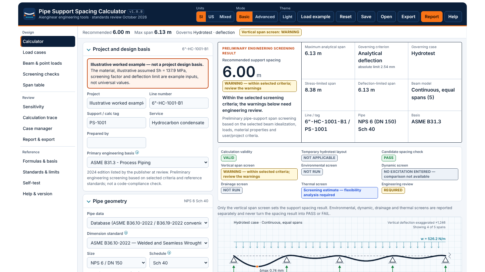
For a 6-inch Sch 40 condensate line with 50 mm insulation, a 2.54 mm sag limit and five equal spans, the hydrotest governs and the recommended spacing is 6.0 m. Use the calculator below for your own line, or the new Span table panel for every size at once.
How to use the calculator
- Pick the pipe. Choose NPS and schedule from ASME B36.10 or B36.19, or enter a custom OD and wall, then set corrosion allowance.
- Set material and temperature. Enter E and the allowable stress Sh from your code table, or a temperature table that the tool interpolates.
- Describe contents and coverings. Fluid density and fill, insulation, cladding, fireproofing, tracing and attachments.
- Choose the criteria. A stress screening basis and a deflection limit (absolute, L/n or both) from your project specification.
- Choose the beam model and, if you have a layout in mind, a candidate spacing to check.
- Review cases and point loads. Switch on hydrotest, steam or custom cases and place valves on the Beam & point loads panel.
- Read the result and print. Check the warnings, open the Span table for other sizes, and print the engineering report.
Tip: press Load example to restore the worked example on this page, then change one input at a time and watch the What changed the result? panel.
What is new in version 1.0.8
Version 1.0.8 is a convenience and standards-review release. The engineering method is unchanged, and every earlier regression test still runs.
Aienginear Table 1
Pipe support spacing calculator v1.0.8 changes
Compared with the September 2026 release (v1.0.7)
| Area | v1.0.7 | v1.0.8 |
|---|---|---|
| Span table | Not available | New panel: spans for every NPS on your basis, printable and CSV |
| Embedded view | Guide repeated inside the calculator frame | Calculator frame shows the tool only; the guide lives on this page |
| Standards review | September 2026 | October 2026: B31.3-2024, B31.1-2024, MSS SP-58-2025, B36.10/B36.19-2022 |
| Printable outputs | Engineering report | Report plus branded span table and printable tables and figures on this page |
| Self-test | 393 checks | 400 checks including span-table regression against the worked example |
| Calculation method | Direct stiffness beam solver | Unchanged; all previous regression tests retained |
How pipe support span is calculated
Between two supports a horizontal pipe behaves as a beam under its own weight. Two things can go wrong as the span grows: bending stress rises with L², and sag rises with L⁴. The calculator finds the span at which each reaches its limit, for every enabled load case, and keeps the shortest.
Stress-limited span
The peak moment under a uniform load is M = Cm·w·L², and the bending stress is M/Z. Setting the stress equal to the screening criterion S gives:
S can be a user-selected factor times Sh (for example 0.25·Sh, a project choice rather than a code value), a direct value, or a simplified sustained screen W·Sh − P·Do/(4t). None of these replaces the sustained-stress check of a full piping stress analysis.
Deflection-limited span
Mid-span sag is δ = Cd·w·L⁴/(E·I). For a fixed sag limit δa:
Sag is not only cosmetic. It creates pockets where condensate or liquid collects, prevents a line from draining, and shifts load onto the neighbouring supports.
Weight of pipe, contents and insulation
Each term is a mass per metre multiplied by g. Coverings are modelled as real annuli, so 50 mm of insulation on a small bore is weighted correctly instead of as a fixed percentage of pipe weight.
Aienginear Table 2
Distributed load terms used in the span calculation
Every term is evaluated per load case
| Load term | Formula | Note |
|---|---|---|
| Pipe metal | m = π/4 · (OD² − ID²) · ρpipe | Nominal wall for weight; corroded wall for I and Z |
| Contents | m = π/4 · ID² · fill · ρfluid | Corroded bore, so slightly heavier |
| Insulation | m = π/4 · (D1² − OD²) · ρins, D1 = OD + 2t | True annulus, not a percentage of pipe weight |
| Cladding, fireproofing | further annuli on D1, then D2 | Each layer sits on the one below |
| Tracing, attachments, extra | entered as kg/m or N/m | Added directly |
| Total distributed load | w = g · Σm · case factor | g = 9.80665 m/s² |
Beam models and coefficients
The moment and deflection coefficients must come from the same beam. Pairing the continuous-span moment wL²/10 with the simple-span sag 5wL⁴/384 mixes two different structures and gives a span that neither beam would have. The calculator solves the chosen model with a direct stiffness solver and shows its own coefficients.
Aienginear Table 3
Uniform-load beam coefficients
M = Cm·w·L², δ = Cd·w·L⁴/(EI), R = Cr·w·L (maximum values)
| Beam model | Cm | Cd | Max reaction | Typical use |
|---|---|---|---|---|
| Simply supported | 0.125 | 0.01302 | 0.50 wL | Isolated span; useful screening idealization |
| Two equal spans | 0.125 | 0.00542 | 1.25 wL | Short runs between two anchors |
| Three equal spans | 0.100 | 0.00688 | 1.10 wL | Idealized straight run |
| Five equal spans | 0.1053 | 0.00657 | 1.13 wL | Long straight run (worked example) |
| Propped (fixed-pinned) | 0.125 | 0.00542 | 0.625 wL | Span next to an anchor, if justified |
| Fixed-fixed | 0.0833 | 0.00260 | 0.50 wL | Only where real restraint justifies it |
Coefficients from an independent three-moment calculation; the calculator’s solver reproduces them in its self-test. Real runs differ because of unequal spans, bends, anchors, guides and friction.
Choosing a deflection limit
There is no single code-mandated sag for every piping system. Common practice is an absolute limit of about 2.5 mm (0.1 in) for process lines that must drain, sometimes relaxed for utility lines, or a span ratio such as L/240 or L/360. The choice matters: on the worked-example line a 2.54 mm limit gives a 6.13 m maximum span, while L/240 lets the span grow until bending stress governs at 8.38 m. Take the value from your project specification and record it on the report.
Operating, empty and hydrotest cases
Six cases can be run side by side: empty, normal operating, full liquid, hydrotest, steam or gas, and a custom case. Each has its own temperature, contents, covering flag and load factor. The governing permanent case sets the spacing.
Hydrotest often controls gas, steam and light-hydrocarbon lines because water is heavier than the service fluid. If temporary supports will be installed for the test, tick that option: the hydrotest is still reported with the temporary spacing it needs, but it no longer shortens the permanent layout. In the worked example this changes the governing case to operating and the maximum span to 6.30 m.
Valves, flanges and concentrated loads
A point load at mid-span creates a moment of P·L/4, twice that of the same weight spread evenly. The calculator never smears valves into a uniform load. Each item sits at its own position, either at a fixed distance from the left support (the default, matching a real valve location) or at a fixed fraction of the span, and the span is found by bisection. A load placed on a support goes straight into that reaction. Negative reactions are reported as uplift, never set to zero.
Good practice: locate a support close to heavy valves, strainers and flanged specialty items rather than relying on the span check alone. In the worked example a single 1.5 kN valve at 2.25 m reduces the recommended spacing from 6.0 m to 4.5 m.
Worked example: 6-inch condensate line
Illustrative example, not a project design basis. NPS 6 Sch 40 carbon steel (OD 168.3 mm, wall 7.11 mm), 1.5 mm corrosion allowance, 80 °C design temperature; 50 mm insulation at 130 kg/m³ with 0.7 mm aluminium cladding; condensate 720 kg/m³; hydrotest water 998 kg/m³ with insulation in place; illustrative Sh = 137.9 MPa with a 0.25 screening factor (34.5 MPa); 2.54 mm sag limit; five equal spans; 0.5 m rounding.
Aienginear Table 4
Worked example results
Reference values derived independently and reproduced by the calculator’s regression test
| Step | Result |
|---|---|
| Corroded wall / bore | 5.61 mm / 157.05 mm |
| I and Z (corroded) | 9,496,433 mm⁴ / 112,868 mm³ |
| Pipe + insulation + cladding | 28.27 + 4.46 + 1.60 kg/m |
| Condensate / test water | 13.95 / 19.33 kg/m |
| w: empty / operating / hydrotest | 337 / 473 / 526 N/m |
| Five-span coefficients | Cm 0.1053, Cd 0.00657 |
| Hydrotest stress-limited span | 8.38 m |
| Hydrotest deflection-limited span | 6.13 m |
| Operating deflection-limited span | 6.30 m |
| Maximum span / recommended spacing | 6.13 m / 6.0 m |
| At a 4.5 m candidate: stress, sag, reaction | 9.9 MPa, 0.74 mm, 2.68 kN |
| Simply supported instead | 5.17 m (5.0 m spacing) |
| Hydrotest on temporary supports | operating governs: 6.30 m (6.0 m spacing) |
| With a 1.5 kN valve at 2.25 m | 5.00 m (4.5 m spacing) |
Deflection in the hydrotest case governs at 6.13 m, so the recommended spacing is 6.0 m. A hand check: L = (0.00254 × 203×10⁹ × 9.496×10⁻⁶ / (0.00657 × 526))1/4 = 6.13 m.
Pipe support span table by NPS
The table below was generated with the calculator’s new Span table panel using the worked-example basis for every Sch 40 size. It shows how strongly span depends on size and why one published table cannot fit every line. Open the Span table panel above to regenerate it for your own material, insulation, fluid and criteria.
Aienginear Table 5
Pipe support span table, Sch 40 carbon steel (worked-example basis)
Five equal spans, 50 mm insulation + cladding, condensate service, water hydrotest, 2.54 mm sag limit, 1.5 mm corrosion allowance
| NPS (DN) | OD mm | Wall mm | w operating N/m | Stress-limited m | Deflection-limited m | Recommended m |
|---|---|---|---|---|---|---|
| 1/2 (15) | 21.34 | 2.77 | 35.8 | 1.84 | 1.72 | 1.50 |
| 3/4 (20) | 26.67 | 2.87 | 42.5 | 2.22 | 1.99 | 1.50 |
| 1 (25) | 33.40 | 3.38 | 53.9 | 2.85 | 2.39 | 2.00 |
| 1-1/4 (32) | 42.16 | 3.56 | 68.0 | 3.38 | 2.76 | 2.50 |
| 1-1/2 (40) | 48.26 | 3.68 | 78.7 | 3.71 | 2.99 | 2.50 |
| 2 (50) | 60.32 | 3.91 | 101.9 | 4.29 | 3.40 | 3.00 |
| 2-1/2 (65) | 73.02 | 5.16 | 143.3 | 5.32 | 3.96 | 3.50 |
| 3 (80) | 88.90 | 5.49 | 185.9 | 5.95 | 4.41 | 4.00 |
| 4 (100) | 114.30 | 6.02 | 264.5 | 6.84 | 5.03 | 5.00 |
| 6 (150) | 168.27 | 7.11 | 473.4 | 8.38 | 6.13 | 6.00 |
| 8 (200) | 219.07 | 8.18 | 724.3 | 9.61 | 7.02 | 7.00 |
| 10 (250) | 273.05 | 9.27 | 1,045.6 | 10.73 | 7.83 | 7.50 |
| 12 (300) | 323.85 | 10.31 | 1,401.6 | 11.69 | 8.53 | 8.50 |
| 14 (350) | 355.60 | 11.13 | 1,662.0 | 12.31 | 8.96 | 8.50 |
| 16 (400) | 406.40 | 12.70 | 2,147.9 | 13.33 | 9.64 | 9.50 |
| 18 (450) | 457.20 | 14.27 | 2,696.4 | 14.28 | 10.28 | 10.00 |
| 20 (500) | 508.00 | 15.09 | 3,227.9 | 14.95 | 10.80 | 10.50 |
| 24 (600) | 609.60 | 17.48 | 4,526.4 | 16.41 | 11.84 | 11.50 |
Preliminary screening values for the stated basis only; hydrotest deflection governs every size. Not a published support-spacing table and not for direct design use.
Published span tables vs calculated spans
ASME B31.1-2024 contains a table of suggested maximum spacing between supports, built on stated assumptions about pipe, contents and sag. ASME B31.3-2024 gives no span table, and ANSI/MSS SP-58-2025, which absorbed the retired MSS SP-69, covers support types, design and installation rather than one spacing for every system. Many owners also publish their own span tables.
These tables are a fast first check, but they rarely cover heavy insulation, corroded walls, dense fluids, high temperature or valves. The calculator keeps any table value you enter as a separate reference and only uses it as a limit if you choose to.
Thermal, vibration, wind and drainage screens
- Thermal expansion: ΔL = α·L·ΔT for the run, plus friction at sliding supports.
- Natural frequency: span frequency including point masses (Dunkerley), compared with excitation frequencies you enter.
- Wind and seismic: lateral bending combined with weight stress.
- Drainage: compares line slope with the steepest upward slope of the sagging pipe to predict pockets.
These are screening estimates in their own status blocks. They never change the vertical span result and do not replace flexibility, vibration or structural qualification.
Common pipe span mistakes
- Using the fourth-root formula with an L/n deflection limit.
- Mixing wL²/10 moment with the simple-span sag 5wL⁴/384.
- Calculating I and Z on the nominal wall when the line has a corrosion allowance.
- Ignoring the hydrotest on gas or steam lines.
- Treating a valve as extra uniform load.
- Applying a table span to an insulated or heavier-than-water line.
- Assuming fixed ends on ordinary resting supports.
How this calculator compares
Aienginear Table 6
Aienginear calculator vs typical span tables and simple online tools
Feature comparison based on common practice, not on any single product
| Feature | Typical static table / simple tool | Aienginear PSSC v1.0.8 |
|---|---|---|
| Basis of span | Fixed assumptions (water-filled, bare pipe, one deflection value) | Your pipe, wall, corrosion, contents, insulation layers and criteria |
| Stress and deflection | Usually one combined value | Both spans reported for every case, governing one explained |
| Load cases | One | Empty, operating, full, hydrotest, steam/gas and custom, side by side |
| Valves and point loads | Not covered | Solved at their real position; layout conflicts flagged |
| Beam model | Not stated or simple span only | Simple, 2 to 10 equal spans, propped, fixed or user coefficients |
| Support reactions | Not given | Every support, every case, with equilibrium check and uplift detection |
| Multi-size table | Static, cannot be changed | Regenerated instantly for your basis; print and CSV |
| Transparency | Result only | Full calculation trace, formulas, sensitivity and 400 self-tests |
| Output | Screen value | Printable engineering report, CSV, JSON and project files |
Assumptions and limitations
- Straight horizontal pipe on idealized supports; Euler–Bernoulli bending, small deflection, linear elastic.
- No support settlement, local clamp stress, fitting flexibility, nozzle loads, spring design or structural steel checks.
- Thermal, seismic, vibration and drainage results are screens only.
- Polymer and composite pipe need long-term manufacturer data; creep is not modelled.
- Buried and subsea pipe are out of scope.
Standards and references
Aienginear Table 7
Standards referenced by the pipe support spacing calculator
Editions confirmed at the October 2026 review; verify against your contract documents
| Document | Title | Role in this tool |
|---|---|---|
| ASME B31.3-2024 | Process Piping | Allowable stress basis for many process lines; no universal span table |
| ASME B31.1-2024 | Power Piping | Includes a suggested support spacing table with stated assumptions |
| ANSI/MSS SP-58-2025 | Pipe Hangers and Supports | Materials, design, selection and installation of supports; replaces SP-69 content |
| ASME B36.10-2022 | Welded and Seamless Wrought Steel Pipe | Carbon and alloy steel dimensions used in the calculator |
| ASME B36.19-2022 | Stainless Steel Pipe | Stainless dimensions used in the calculator |
| ASME B31J-2023 | SIFs and flexibility factors | Stress analysis reference, not a spacing standard |
| MSS SP-127 | Bracing for piping systems | Seismic, wind and dynamic bracing reference |
| ISO 14692 | GRP piping | Support considerations for composite pipe |
Video explainer
Quick quiz: test your pipe span knowledge
Related Aienginear calculators and guides
Frequently asked questions
What is pipe support spacing?
Pipe support spacing is the distance between neighbouring supports on a horizontal pipe run. It is set by the bending stress the pipe can carry, by how far it may sag between supports, by concentrated loads such as valves, and by layout rules in the project specification.
How do I calculate the maximum span between pipe supports?
Add up the load per metre from pipe, contents, insulation and attachments. Solve for the span at which bending stress reaches your screening criterion and the span at which sag reaches your deflection limit. The shorter span governs, and you round it down to a practical spacing.
Does stress or deflection usually govern pipe span?
With a tight sag limit such as 2.5 mm, deflection usually governs for steel pipe; with a span-ratio limit such as L/240 or a low stress criterion, stress can govern. The calculator reports both spans for every case and states which one controls.
Why does the hydrotest sometimes govern support spacing?
Test water is heavier than gas, steam or light hydrocarbons, so a vapour or light-liquid line can carry its highest weight during the test. If temporary supports are planned for the test, mark the hydrotest as temporary so it no longer shortens the permanent spacing.
What deflection limit should be used for pipe supports?
Use the limit in the project specification. Many companies use an absolute sag of about 2.5 mm (0.1 in) or a span ratio; no single value applies to every system. The calculator accepts an absolute limit, L/n, or the lesser of both.
Why is the L/n deflection formula a cube root?
With a fixed sag limit the span comes from a fourth root because sag grows with L to the fourth power. When the limit itself is L/n, one power of L cancels, leaving a cube root. Mixing the two forms is a common spreadsheet error.
How much do valves and flanges reduce the support span?
A concentrated load produces roughly twice the bending moment of the same weight spread evenly. In the worked example a 1.5 kN valve 2.25 m from a support cuts the maximum span from 6.13 m to 5.00 m. Place a support close to heavy items.
Is there an ASME table of pipe support spacing?
ASME B31.1 contains a table of suggested support spacing with stated assumptions; ASME B31.3 has none. MSS SP-58-2025 covers hanger and support design and selection. Calculated spans let you check conditions those tables do not cover, such as heavy insulation, corroded walls or valves.
Should corrosion allowance be removed when calculating pipe span?
Usually yes. Section properties are calculated on the corroded wall, which lowers I and Z and shortens the span, while weight uses the nominal wall. The calculator applies this conservative combination by default.
What is the multi-size span table?
The Span table panel repeats the full calculation for every NPS in the selected standard using your current basis, and lists stress-limited, deflection-limited and maximum spans with the recommended spacing. It can be printed with Aienginear branding or exported as CSV.
Can I use this calculator for plastic or FRP pipe?
Only as a screen with manufacturer data. Polymer and composite pipe has a low, time-dependent modulus, so enter the long-term modulus at temperature and compare with the manufacturer span tables; continuous support is often needed.
Is this pipe support spacing calculator code compliant?
No. It is a preliminary engineering screening tool. Final support spacing must be confirmed by piping stress analysis, support design and structural checks to the governing code and project specification.
Is my data uploaded anywhere?
No. All calculations run in your browser. Inputs stay in your browser storage or in files you choose to save.
Key takeaways
- Span is the shorter of the stress-limited and deflection-limited spans over every load case.
- Use the corroded wall for I and Z, real annuli for coverings and one beam model for both coefficients.
- Check the hydrotest, and place supports near valves.
- Generate a span table for your own basis instead of borrowing one built on different assumptions.
Engineering disclaimer. This calculator provides preliminary engineering screening based on the selected beam idealization, loads, material properties and user/project criteria. It is not a complete piping stress/flexibility analysis, pipe-support design, structural design, seismic/wind design, vibration qualification or code-compliance certification. Final engineering decisions require project-specific specifications, applicable codes and standards, verified material and dimensional data, support details, structural verification and qualified engineering review.

Written by Muhammad Raza
Founder of Aienginear. Mechanical engineer (BSc, UET Lahore) and Head of Projects with 18+ years managing piping, mechanical installation, plant shutdowns and turnarounds in power, cement, fertilizer and oil & gas plants.