
Quick answer: how do you calculate flow through an orifice plate?
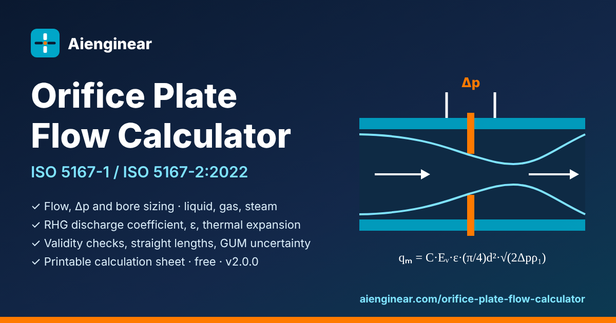
An orifice plate meter infers flow from the differential pressure (Δp) across a sharp-edged hole. Under ISO 5167-1 and ISO 5167-2:2022 the mass flow rate is:
where C is the Reader-Harris/Gallagher discharge coefficient (about 0.60), β = d/D, ε is the expansibility factor (1 for liquids), d is the bore and ρ1 the upstream density. Because C depends on the Reynolds number, which depends on the flow, the solution is iterative. The free Aienginear calculator below does that iteration for liquid, gas and steam, and also sizes the bore, checks the ISO limits, estimates uncertainty and prints a branded calculation sheet.
Key takeaways
- Flow is proportional to √Δp, so a 10:1 DP span gives only about 3.2:1 flow turndown at good accuracy.
- ISO 5167-2:2022 keeps the Reader-Harris/Gallagher equation and the 2003 expansibility equation. The main changes are a tighter bore-edge rule for β < 0.2, corrected two-45°-bend spacing, a clearer tee definition, and a new clause on flow calibration.
- Stay inside 50 mm ≤ D ≤ 1000 mm, d ≥ 12.5 mm, 0.10 ≤ β ≤ 0.75, the Reynolds limits, and p2/p1 ≥ 0.75. Otherwise the standard’s uncertainty claims no longer apply.
- With good installation, the discharge coefficient uncertainty is 0.5 % for 0.2 ≤ β ≤ 0.6. Straight-pipe lengths usually decide whether you actually get it.
- Permanent pressure loss is typically 45 % to 95 % of Δp. Over a plant’s life it costs real energy, and the calculator puts a number on it.
Orifice plate flow calculator (ISO 5167-2:2022)
Choose one of three modes: Flow from Δp (rating an existing plate), Δp from flow (choosing a transmitter range), or Size the bore (designing a new plate). Every unit selector converts the value you have already typed. The tool runs a 21-case self-test every time it loads, and the badge in its header turns green only when all cases pass. Your inputs are saved in your own browser and never leave your device.
What the v2.0.0 calculator adds
- Three solve modes: flow, differential pressure and bore sizing. Each uses a bracketed solver, so the tool never returns a silent extrapolation.
- Thermal expansion correction of D and d from 20 °C to operating temperature, for carbon steel, 304/316, duplex, Monel and Hastelloy. The bore to machine is reported at 20 °C.
- Gas density from p, T, M and Z, with actual, Nm³/h, Sm³/h, SCFH and MMSCFD outputs, plus steam presets taken from IAPWS-IF97 values.
- An ISO 5167-2:2022 validity table: D, d, β, Reynolds number, pressure ratio, edge and plate thickness (including the new e/d ≤ 0.1 rule for β < 0.2), roughness, cavitation screening and transmitter range.
- Straight-length requirements for 12 upstream fittings, at zero and at 0.5 % additional uncertainty, compared with the length you actually have.
- An uncertainty budget to ISO 5167-1 and GUM, with sensitivity coefficients and each source’s share of the variance.
- A DP-span curve and transmitter scaling table for square-root extraction, plus a turndown warning.
- Energy cost of the permanent pressure loss per year and over 10 years.
- A printable Aienginear calculation sheet, CSV export, and a JSON project file you can save and reopen. The tool has light and dark themes, works fully offline once loaded, and makes no external calls.
1. How an orifice plate meter works
An orifice plate is a thin, flat disc with a precisely machined, sharp-edged hole, clamped between flanges at right angles to the pipe axis. As the stream approaches the plate it converges, accelerates through the bore and keeps contracting for a short distance downstream, to a minimum jet area called the vena contracta. Energy conservation means that the gain in velocity is paid for with a drop in static pressure, so the pressure at a tapping just downstream of the plate is lower than the pressure upstream. That difference, Δp = p1 − p2, is what the transmitter measures.
Downstream of the vena contracta the jet slows and spreads back to the pipe wall, and some static pressure is recovered. It is not all recovered, because the turbulent mixing and recirculation zones behind the plate dissipate energy. That shortfall is the permanent pressure loss, and it is the price of using an orifice instead of a venturi.
The orifice plate stays the most widely installed differential-pressure meter for three reasons. It has no moving parts. It is fully characterised by an international standard, so a plate built and installed to ISO 5167-2 needs no flow calibration to reach a known uncertainty. And one transmitter design covers liquids, gases and steam from about 50 mm to 1000 mm line size.
2. The ISO 5167 flow equation
ISO 5167-1 combines Bernoulli’s equation and continuity between the upstream tapping and the throat, then corrects the ideal result with two empirical factors. In mass-flow form:
Volume flow at the upstream condition is qv = qm / ρ1. For gas reported at standard or normal conditions, divide qm by the density at those reference conditions, ρref = prefM / (ZrefRTref). D and d must be the values at the operating temperature, so a plate machined at 20 °C has to be corrected for thermal expansion:
| Symbol | Quantity | SI unit | Where it comes from |
|---|---|---|---|
| qm | Mass flow rate | kg/s | Result |
| C | Discharge coefficient | – | Reader-Harris/Gallagher equation, ISO 5167-2 5.3.2.1 |
| Ev | Velocity-of-approach factor | – | 1/√(1−β4) |
| ε | Expansibility (expansion) factor | – | ISO 5167-2 5.3.2.2; equals 1 for liquids |
| β | Diameter ratio d/D | – | Both values at operating temperature |
| d | Orifice bore at operating temperature | m | Measured bore at 20 °C, corrected |
| D | Pipe internal diameter upstream | m | Measured over 0.5D upstream, corrected |
| Δp | Differential pressure | Pa | DP transmitter |
| ρ1 | Fluid density at the upstream tapping | kg/m³ | Lab data, equation of state or steam tables |
| ReD | Pipe Reynolds number 4qm/(πμD) | – | Drives the iteration for C |
Why iteration is needed. C depends on ReD, and ReD depends on qm, which is the unknown. The calculator starts from C = 0.6, works out qm and ReD, updates C, and repeats until C changes by less than 10−12. That normally takes four to six passes. In sizing mode the bore is the unknown. A bracketed bisection on β between 0.02 and 0.85 then finds the single bore that delivers the design flow at the chosen Δp, and the tool reports clearly when no bore in that range can do it.
3. Discharge coefficient: the Reader-Harris/Gallagher equation
The discharge coefficient is the ratio of actual to ideal flow. It mainly accounts for the jet contracting to an area smaller than the bore, plus friction and the exact positions of the tappings. ISO 5167-2 uses the Reader-Harris/Gallagher (RHG, 1998) correlation, which was fitted to a large international database of carefully calibrated plates:
with A = (19 000β/ReD)0.8 and M′2 = 2L′2/(1 − β). If D < 71.12 mm (2.8 in), add 0.011(0.75 − β)(2.8 − D/25.4), with D in mm. The terms each describe one physical effect. The first three give the infinite-Reynolds value. The two ReD terms capture viscous effects, which grow quickly at low Reynolds number and high β. The L1 term corrects for an upstream tap away from the plate face, and the M′2 term for a downstream tap in the pressure-recovery region.
| β | ReD = 104 | 3×10⁴ | 105 | 106 | 107 |
|---|---|---|---|---|---|
| 0.20 | 0.6014 | 0.5990 | 0.5978 | 0.5971 | 0.5969 |
| 0.30 | 0.6049 | 0.6014 | 0.5996 | 0.5984 | 0.5981 |
| 0.40 | 0.6102 | 0.6051 | 0.6024 | 0.6005 | 0.5999 |
| 0.50 | 0.6179 | 0.6102 | 0.6062 | 0.6032 | 0.6021 |
| 0.60 | 0.6278 | 0.6162 | 0.6101 | 0.6052 | 0.6034 |
| 0.70 | 0.6377 | 0.6202 | 0.6110 | 0.6035 | 0.6004 |
| 0.75 | 0.6410 | 0.6196 | 0.6084 | 0.5991 | 0.5953 |
4. Pressure tapping arrangements
ISO 5167-2 recognises three tapping arrangements. All three use the same RHG equation and differ only in L1 (the upstream tap distance divided by D) and L′2 (the downstream distance from the downstream face, divided by D). The calculator sets these values automatically.
| Arrangement | L1 | L′2 | Typical use | Practical notes |
|---|---|---|---|---|
| Corner | 0 | 0 | Small lines, carrier-ring assemblies, European practice | Annular slots average the pressure around the circumference and tolerate slightly disturbed profiles |
| Flange (25.4 mm) | 25.4/D | 25.4/D | Oil and gas, refining, ASME B16.36 orifice flanges | Tap distance is fixed in millimetres, so L1 changes with line size |
| D and D/2 (radius) | 1 | 0.47 | Large lines, water and power plants | Taps are drilled into the pipe wall, so the flange design is independent of the meter |
5. Expansibility factor for gas and steam
When a gas or vapour accelerates through the bore its pressure falls and it expands, so density at the throat is lower than ρ1. The expansibility factor ε corrects for this. ISO 5167-2:2022 keeps the equation introduced in 2003, which is based on the upstream tapping pressure:
It is valid only for p2/p1 ≥ 0.75. Its relative expanded uncertainty is 3.5Δp/(κp1) %. Practical guidance: keep Δp below about 25 kPa for each bar of absolute line pressure (Δp/p1 ≤ 0.25 is the hard limit, and lower is better). For steam use the isentropic exponent at the actual state. About 1.3 is typical for superheated steam, and published values for dry saturated steam are often lower, so take κ from your steam-table source.
| β | p2/p1 = 0.98 | 0.95 | 0.90 | 0.85 | 0.80 | 0.75 |
|---|---|---|---|---|---|---|
| 0.30 | 0.9946 | 0.9863 | 0.9725 | 0.9585 | 0.9443 | 0.9299 |
| 0.50 | 0.9943 | 0.9857 | 0.9711 | 0.9564 | 0.9415 | 0.9264 |
| 0.60 | 0.9938 | 0.9845 | 0.9689 | 0.9530 | 0.9369 | 0.9206 |
| 0.70 | 0.9928 | 0.9820 | 0.9637 | 0.9452 | 0.9265 | 0.9075 |
6. ISO 5167-2 limits of use
The 0.5 % uncertainty that ISO 5167-2 assigns to C applies only inside the database the RHG equation was fitted to. The calculator checks every limit in Table 5 and labels any value outside it as OUTSIDE LIMIT. In that case the result is indicative only, and a flow calibration (clause 7 of the 2022 edition) or a different primary element should be considered.
| Parameter | Corner and D and D/2 taps | Flange taps |
|---|---|---|
| Bore d | d ≥ 12.5 mm | d ≥ 12.5 mm |
| Pipe ID D | 50 mm ≤ D ≤ 1000 mm | 50 mm ≤ D ≤ 1000 mm |
| Diameter ratio β | 0.10 ≤ β ≤ 0.75 | 0.10 ≤ β ≤ 0.75 |
| Reynolds number ReD | ≥ 5000 for 0.10 ≤ β ≤ 0.56; ≥ 16 000β2 for β > 0.56 | ≥ 5000 and ≥ 170β2D (D in mm) |
| Pressure ratio (gas, steam) | p2/p1 ≥ 0.75 | p2/p1 ≥ 0.75 |
| Pipe roughness | Upstream 10D within ISO 5167-2 Table 2 limits on 104Ra/D (tighter as β rises) | |
| Flow | Single-phase, steady or slowly varying, subsonic, pipe running full, no swirl | |
7. What changed in ISO 5167-2:2022
The second edition, published in 2022, replaces ISO 5167-2:2003. Its foreword states that the technical changes are deliberately limited. The equations used by most calculators are unchanged, but several geometry and installation rules are tighter or clearer:
| Topic | 2003 edition | 2022 edition | Effect in this calculator |
|---|---|---|---|
| Discharge coefficient | RHG (1998) | RHG unchanged | Same equation, verified in the self-test |
| Expansibility ε | 2003 equation, p2/p1 ≥ 0.75 | Unchanged | Same equation and limit |
| Bore edge thickness for β < 0.2 | 0.005D ≤ e ≤ 0.02D | Also e/d ≤ 0.1 | Extra check when β < 0.2 |
| Two 45° bends in S-configuration | Spacing S ≥ 2D (an error) | Corrected to S ≥ 22D | Noted in the straight-length guidance |
| Tee upstream | Loosely defined | Equal tee, flow from the branch into the run | Fitting description updated |
| Multiple fittings | Wording open to misreading | Clarified, requirements unchanged | No numerical change |
| Flow calibration | Not covered | New clause 7, including calibration uncertainty analysis | Advice when outside limits |
| Uncertainty wording | 95 % confidence | Relative expanded uncertainty, k = 2 (values unchanged) | Budget reported at k = 2 |
8. Orifice plate geometry and tolerances
The standard’s uncertainty holds only for a plate that matches its geometry rules. Most field errors come from plates that started out compliant but were later damaged, installed back-to-front, or left with a worn edge.
| Feature | Requirement | Why it matters |
|---|---|---|
| Upstream face flatness | Slope less than 0.5 % when installed under no differential | A dished plate changes C, and buckling under high Δp is a known failure mode |
| Upstream face roughness | Ra < 10−4d within a circle of diameter at least 1.5d | Roughness alters the boundary layer that approaches the edge |
| Edge thickness e | 0.005D to 0.02D; for β < 0.2, also e ≤ 0.1d (2022) | A thick edge behaves like a short nozzle and C rises |
| Plate thickness E | e to 0.05D (up to 3.2 mm allowed for 50 mm ≤ D ≤ 64 mm) | Has to resist deflection under maximum Δp |
| Bevel angle F | 45° ± 15°, required if E > e | Keeps the jet from reattaching to the bore |
| Upstream edge G | Sharp: edge radius ≤ 0.0004d | A rounded edge raises C, typically by 1 % to 2 % on a worn plate |
| Bore diameter d | Mean of at least four measurements; each within 0.05 % of the mean | qm varies roughly with d2 |
| Bore cylindricity | No diameter differs by more than 0.05 % from the mean | An oval bore biases C |
9. Worked examples
All three examples below can be reproduced in the calculator. The numbers shown are the calculator’s own output and were cross-checked against an independent implementation of the same ISO 5167-2 equations.
Example 1: Water in a 4 in Schedule 40 line (rating)
A carbon steel NPS 4 Sch 40 line (D = 102.26 mm) carries water at 20 °C (ρ = 998.21 kg/m³, μ = 1.002 cP). A stainless steel plate with flange taps has d = 51.13 mm (β = 0.50), and the transmitter reads 25 kPa. Because the fluid is at 20 °C, no thermal correction is needed.
| Step | Calculation | Result |
|---|---|---|
| 1. Velocity of approach | Ev = 1/√(1 − 0.54) | 1.0328 |
| 2. Ideal-flow group | (π/4)(0.05113)2 √(2 × 25 000 × 998.21) | 14.508 kg/s |
| 3. First pass, C = 0.6 | qm = 0.6 × 1.0328 × 14.508 | 8.99 kg/s |
| 4. ReD then C (RHG, flange) | Iterate to convergence (5 passes) | C = 0.60594 |
| 5. Mass flow | qm = C Ev × 14.508 | 9.0778 kg/s = 32 680 kg/h |
| 6. Volume flow | qm/ρ | 32.74 m³/h (144.1 US gpm) |
| 7. Reynolds number | 4qm/(πμD) | 112 802 (limit 9 459) |
| 8. Pipe velocity | qv/(πD2/4) | 1.11 m/s |
| 9. Permanent pressure loss | ISO 5167-2 5.4 ratio × Δp | 18.31 kPa (73.2 %) |
| 10. Uncertainty (k = 2) | UC 0.5 %, UD 0.4 %, Ud 0.07 %, UΔp 0.2 %, Uρ 0.2 % | ± 0.54 % |
Example 2: Natural gas at 40 bar(a) in a 6 in line (rating with standard volume)
Natural gas (M = 17.4 kg/kmol, Z = 0.92, μ = 0.011 cP, κ = 1.30) flows at 40 bar(a) and 20 °C in NPS 6 Sch 40 (D = 154.08 mm). The plate has d = 92.45 mm (β = 0.600) with flange taps, and Δp = 50 kPa.
| Quantity | How it is obtained | Result |
|---|---|---|
| Upstream density ρ1 | p1M/(ZRT) = 40×105 × 17.4/(0.92 × 8314.46 × 293.15) | 31.04 kg/m³ |
| Pressure ratio p2/p1 | (4000 − 50)/4000 | 0.9875 |
| Expansibility ε | ISO 5167-2:2022 equation | 0.99615 |
| Discharge coefficient C | RHG, flange taps, converged | 0.60393 |
| Mass flow qm | ISO 5167-1 equation | 7.626 kg/s = 27 454 kg/h |
| Actual volume flow | qm/ρ1 | 884.5 m³/h |
| Standard flow (15 °C, 101.325 kPa, Zb = 0.998) | qm/ρs | 37 233 Sm³/h |
| Normal flow (0 °C, 101.325 kPa) | qm/ρn | 35 295 Nm³/h |
| US standard (60 °F, 14.73 psia) | qm/ρb | 31.54 MMSCFD |
| ReD / pipe velocity | – | 5.73×10⁶ / 13.2 m/s |
| Permanent pressure loss | ISO 5167-2 5.4 | 31.5 kPa (63 %) |
Example 3: Sizing a bore for saturated steam at 10 bar(a)
The task is to size a plate for 10 000 kg/h of dry saturated steam at 10 bar(a) and 179.9 °C (ρ = 5.145 kg/m³, μ = 0.015 cP, κ = 1.3) in carbon steel NPS 6 Sch 40, with flange taps and a 316 stainless plate. The transmitter is ranged 0 to 25 kPa at maximum flow.
| Quantity | Note | Result |
|---|---|---|
| Pipe ID at 179.9 °C | 154.08 × [1 + 11.16×10−6 × 159.9] | 154.35 mm |
| Required β at operating temperature | Bisection on β with C and ε updated each pass | 0.6622 |
| Bore at 179.9 °C | βD | 102.22 mm |
| Bore to machine at 20 °C | d / [1 + 16.65×10−6 × 159.9] | 101.95 mm |
| C / ε | RHG / ISO 5167-2:2022 | 0.60486 / 0.99162 |
| ReD | Limit 170β2D = 11 507 | 1.53×10⁶ |
| Pipe velocity | Within a typical steam velocity of 35 m/s or less | 28.9 m/s |
| Permanent pressure loss | – | 13.97 kPa |
10. Permanent pressure loss and energy cost
ISO 5167-2 clause 5.4 gives the permanent loss as a fraction of Δp:
| β | 0.20 | 0.30 | 0.40 | 0.50 | 0.60 | 0.70 | 0.75 |
|---|---|---|---|---|---|---|---|
| Δϕ/Δp | 95 % | 90 % | 82 % | 73 % | 63 % | 51 % | 45 % |
| Venturi tube (typical) | 5 % to 20 % of Δp | ||||||
The calculator’s Energy cost tab converts the loss into money: power = qv × Δϕ / η. For Example 1 (water), with 8000 h a year, η = 70 % and 0.12 per kWh, the loss costs about 1 900 kWh, or roughly 230 a year, which is negligible. For Example 2 (gas at 884 m³/h actual), the same assumptions give about 11 kW of compressor power, close to 88 000 kWh or about 10 600 a year. That is why large gas and steam meters are often specified as venturis, or with a lower design Δp.
11. Straight lengths and flow conditioners
The RHG equation assumes a fully developed, swirl-free velocity profile. Fittings upstream distort that profile, and the distortion decays only slowly. ISO 5167-2 Table 3 therefore sets minimum straight lengths between the plate and the nearest fitting. The values depend on β, and a second set of shorter lengths is allowed if you accept an extra 0.5 % on the C uncertainty, added arithmetically.
| Upstream fitting | β ≤ 0.20 | 0.40 | 0.50 | 0.60 | 0.67 | 0.75 |
|---|---|---|---|---|---|---|
| Single 90° bend, or two in any plane (S > 30D) | 6 (3) | 16 (3) | 22 (9) | 42 (13) | 44 (20) | 44 (20) |
| Two 90° bends, perpendicular planes (30D ≥ S ≥ 5D) | 19 (18) | 44 (18) | 44 (18) | 44 (18) | 44 (20) | 44 (20) |
| Single 90° tee (flow from branch into run) | 3 | 9 (3) | 19 (9) | 29 (18) | 36 (18) | 44 (18) |
| Concentric reducer 2D to D over 1.5D to 3D | 5 | 5 | 8 (5) | 9 (5) | 12 (6) | 13 (8) |
| Concentric expander 0.5D to D over D to 2D | 6 | 12 (8) | 20 (9) | 26 (11) | 28 (14) | 36 (18) |
| Full-bore ball or gate valve, fully open | 12 (6) | 12 (6) | 12 (6) | 14 (7) | 18 (9) | 24 (12) |
| Abrupt symmetrical reduction | 30 (15) for all β | |||||
| Thermowell, diameter ≤ 0.03D / 0.03D to 0.13D | 5 (3) / 20 (10) | |||||
| Downstream, any fitting above | 4 (2) | 6 (3) | 6 (3) | 7 (3.5) | 7 (3.5) | 8 (4) |
Where the space is not available, there are four options: lower β (shorter lengths), accept the 0.5 % penalty, fit a compliant flow conditioner (ISO 5167-1/-2 Annex C, for example a perforated plate that has passed the compliance test), or move the meter. Control valves should always be downstream of the meter. A partly open valve upstream generates swirl that persists for well over 100D.
12. Measurement uncertainty
ISO 5167-1 combines the relative uncertainties of each input as a root-sum-square. Each term is weighted by its sensitivity coefficient:
| Condition | UC |
|---|---|
| 0.10 ≤ β < 0.20 | (0.7 − β) % |
| 0.20 ≤ β ≤ 0.60 | 0.5 % |
| 0.60 < β ≤ 0.75 | (1.667β − 0.5) % |
| Add if D < 71.12 mm | + 0.9(0.75 − β)(2.8 − D/25.4) % |
| Add if β > 0.5 and ReD < 10 000 | + 0.5 % |
| Add if reduced straight lengths are used | + 0.5 % |
| Expansibility, Uε | 3.5Δp/(κp1) % |
In practice the discharge coefficient usually dominates, at about 85 % of the variance in Example 1. The transmitter term grows quickly at low flow, because a fixed percentage of span becomes a larger percentage of a small reading. At 10 % of span, a 0.1 % of span transmitter contributes 1 % of reading in Δp, or 0.5 % in flow. A sound overall design target for a standard-compliant plate is ±0.6 % to ±1 % of mass flow at k = 2. Achieving it in service also needs a correct density value, which for gases often controls the result.
13. DP range, square-root extraction and turndown
Good practice is to choose the transmitter range so that maximum flow sits near 100 % of span and normal flow at roughly 70 % to 80 % of flow (50 % to 65 % of DP). Common ranges are 0 to 25 kPa (100 inH2O) and 0 to 50 kPa (200 inH2O) for liquids, and 0 to 62 kPa (250 inH2O) for high-pressure gas. Do square-root extraction in one place only, either in the transmitter or in the DCS, never both. Apply a low-flow cut-off near 5 % to 10 % of flow, because noise is amplified near zero. If the application needs more than about 4:1 turndown, consider two stacked transmitters, a smart transmitter with high rangeability, or a different meter.
14. Installation and impulse lines
A correct calculation is wasted if the plate or the impulse lines are installed badly. Impulse-line orientation depends on the fluid. The goal is to keep gas out of liquid lines, liquid out of gas lines, and live steam away from the transmitter.
| Item | Requirement or good practice |
|---|---|
| Plate orientation | Sharp edge upstream, bevel downstream, and tab stamped with tag, d at 20 °C, β, material and an “INLET” arrow |
| Concentricity | Bore centred to within 0.0025D/(0.1 + 2.3β4) of the pipe axis (ISO 5167-2 6.5) |
| Gaskets | Must not protrude into the bore or across the tappings, and must be thin |
| Pipe upstream | Circular, measured ID over at least 0.5D upstream, no welds or steps inside 2D |
| Drain and vent holes | Avoid where possible. If used, size and position them per ISO 5167-2 and allow for them in the calculation |
| Vertical runs | Liquid flowing upward and gas flowing downward keep the pipe full and self-clean |
| Hot service | Fill legs for steam and condensables, and protect the transmitter from temperature beyond its rating |
| Commissioning | Zero the transmitter with the equalising valve open at line pressure, and check both legs are free of trapped gas or liquid |
15. Orifice plate vs venturi vs nozzle vs other flowmeters
| Attribute | Orifice plate | Venturi tube | Flow nozzle | Coriolis / ultrasonic |
|---|---|---|---|---|
| Standard | ISO 5167-2, ASME MFC-3M, AGA 3 | ISO 5167-4 | ISO 5167-3 | ISO 10790 / ISO 17089, AGA 9 |
| Typical uncertainty of C | 0.5 % to 0.7 % | 0.7 % to 1.5 % | 0.8 % to 1.2 % | 0.1 % to 0.5 % of reading (calibrated) |
| Permanent loss | High (45 % to 95 % of Δp) | Low (5 % to 20 %) | Medium (30 % to 80 %) | Very low to moderate |
| Straight run needed | Long | Short to medium | Medium | Short (Coriolis) to medium |
| Capital cost | Lowest | High | Medium | High |
| Bore change | Easy (swap plate or use a dual-chamber fitting) | Not possible | Difficult | Not applicable |
| Dirty or erosive service | Poor (edge wear) | Good | Good (high-velocity steam) | Varies |
| Calculator | This page | Venturi meter calculator | ISO 5167-3 | Vendor sizing |
16. Common design mistakes
- Using nominal pipe size as D. NPS 4 is not 100 mm. Use the actual schedule ID (102.26 mm for Sch 40), and preferably a measured ID.
- Ignoring thermal expansion on hot service. At 300 °C a stainless bore grows by about 0.47 %, which is a flow error of about 1 %.
- Using standard density in the equation. ρ1 must be the actual density at the upstream tap. Convert to standard volume only afterwards.
- Using gauge pressure in ε, p2/p1 or the gas density calculation, where absolute pressure is required.
- Choosing β > 0.7 to cut the pressure loss, which pushes uncertainty and straight-length needs up sharply. Aim for 0.3 to 0.6.
- Applying square-root extraction twice, once in the transmitter and again in the DCS.
- Too high a Δp on low-pressure gas, so p2/p1 drops below 0.75 and ε becomes uncertain.
- Ignoring plate deflection at high Δp on thin, large plates, which lowers the effective C.
- Using an orifice for two-phase or wet gas without a wet-gas correction (see ISO/TR 11583).
17. Troubleshooting guide
| Symptom | Likely cause | Check or remedy |
|---|---|---|
| Reads several % low | Plate installed backwards, or a worn or rounded edge (C actually higher) | Pull the plate and inspect the edge with a magnifier; check the INLET marking |
| Reads high | Partially blocked bore, or debris on the upstream face | Inspect, clean, and fit a strainer upstream |
| Noisy or erratic signal | Gas in liquid legs, liquid in gas legs, or pulsation | Vent or drain the legs, re-slope them, and add damping or a pulsation dampener |
| Zero shift | Unequal fill or temperature between legs | Re-fill the legs, insulate or trace both legs equally, and re-zero at line pressure |
| Mass balance does not close | Wrong density, Z or units in the DCS | Compare the DCS constants with this calculator’s report, and check the reference conditions |
| Disagreement after a rate change | Operating below the Reynolds limit, or below 10 % of span | Re-range, use stacked transmitters, or change β |
| Plate found dished | Δp surge or water hammer beyond the plate rating | Use a thicker plate, add a surge-protection review, and check the plate rating |
18. Standards and references
- ISO 5167-1:2022: general principles and requirements, including the flow equation and uncertainty method.
- ISO 5167-2:2022: orifice plates (RHG equation, expansibility, limits, straight lengths, flow calibration).
- ISO/TR 9464:2023: guidelines for the use of ISO 5167:2022.
- ISO/TR 15377:2023: devices beyond the scope of ISO 5167, such as small bores, conical-entrance and quarter-circle plates.
- ASME MFC-3M: measurement of fluid flow in pipes using orifice, nozzle and venturi.
- AGA Report No. 3 / API MPMS Chapter 14.3: concentric square-edged orifice meters for natural gas (custody transfer).
- ISO/IEC Guide 98-3 (GUM): expression of uncertainty in measurement.
- IAPWS-IF97: industrial formulation for the thermodynamic properties of water and steam.
- ASME B36.10M / B36.19M: welded and seamless steel pipe dimensions. See also pipe sizes and schedules.
19. Frequently asked questions
What is the formula for flow through an orifice plate?
Per ISO 5167-1, qm = C/√(1−β4) · ε · (π/4)d2 · √(2Δpρ1). C comes from the Reader-Harris/Gallagher equation, ε is 1 for liquids, and the solution is iterated because C depends on the Reynolds number.
What is a typical discharge coefficient for an orifice plate?
About 0.60 to 0.61 for a sharp-edged concentric plate at high Reynolds number. It rises to 0.62 to 0.64 at low Reynolds number and high β. A rounded or worn edge also raises it.
What is the best beta ratio for an orifice plate?
Between 0.3 and 0.6. In that range the C uncertainty is at its lowest (0.5 %) and straight-length needs stay moderate. ISO 5167-2 allows 0.10 to 0.75.
What changed in ISO 5167-2:2022?
The RHG and expansibility equations did not change. The 2022 edition adds e/d ≤ 0.1 for β < 0.2, corrects the two-45°-bend spacing to 22D, clarifies the tee configuration and the multiple-fitting rules, adds a flow-calibration clause, and states uncertainties as expanded values at k = 2.
Which tappings should I use: flange, corner or D and D/2?
Flange taps are the default in oil, gas and petrochemical plants and suit standard orifice flanges. Corner taps suit small lines and carrier-ring designs. D and D/2 taps suit large lines. All three are covered by the same equation in this calculator.
How much straight pipe does an orifice plate need?
It depends on β and the upstream fitting. For example, a single 90° bend needs 22D at β = 0.5 and 42D at β = 0.6 for zero additional uncertainty. Downstream, 6D to 8D is typical. See Table 12 and the calculator’s Validity & installation tab.
What is the turndown of an orifice flowmeter?
About 3:1 to 4:1 with one transmitter at good accuracy. Because flow varies with the square root of Δp, 10 % of DP span corresponds to 31.6 % of flow.
How accurate is an orifice plate?
A plate built and installed to ISO 5167-2 typically achieves ±0.6 % to ±1 % of mass flow (k = 2) without calibration, provided density and Δp are measured well. Flow calibration can reduce this further.
How do I calculate the orifice bore size?
Select “Size the bore”, enter the design (maximum) flow and the Δp at that flow, which is usually the transmitter URV. The calculator solves for β, then gives the bore to machine at 20 °C after correcting for thermal expansion.
What is the permanent pressure loss across an orifice plate?
About 73 % of Δp at β = 0.5 and 45 % at β = 0.75, calculated from ISO 5167-2 clause 5.4. The calculator also converts it into energy cost per year.
Can an orifice plate measure steam?
Yes. Use the actual steam density from steam tables, the expansibility factor, condensate pots and water-filled impulse legs. For wet steam, apply a wet-gas correction.
Why use absolute pressure in the orifice calculation?
Gas density, ε and the p2/p1 limit all depend on the absolute upstream pressure. Using gauge pressure gives large errors at low line pressure.
Is this calculator suitable for custody transfer?
No. It is a preliminary engineering and design-support tool. Fiscal and custody-transfer metering requires full compliance with ISO 5167, AGA 3 or the contract standard, certified inspection and a validated flow computer.
Does the calculator work in US units?
Yes. The SI ⇄ US button converts every field (in, psia, °F, inH2O, lb/ft³, lb/h, US gpm, SCFH, MMSCFD), and each field also has its own unit selector.
20. Related Aienginear tools and guides
21. Glossary
| Term | Meaning |
|---|---|
| Beta ratio (β) | Bore diameter divided by pipe internal diameter, both at operating temperature |
| Discharge coefficient (C) | Actual flow divided by theoretical flow for the same Δp |
| Expansibility factor (ε) | Correction for gas expansion through the bore; 1 for liquids |
| Vena contracta | Smallest cross-section of the jet, just downstream of the plate |
| Permanent pressure loss (Δϕ) | Pressure not recovered downstream; drives the pumping cost |
| Reynolds number (ReD) | Ratio of inertial to viscous forces, based on pipe ID |
| Isentropic exponent (κ) | Ratio describing reversible adiabatic expansion; about 1.4 for air and 1.3 for natural gas and steam |
| URV | Upper range value of the DP transmitter, usually set at maximum flow |
| Turndown | Ratio of maximum to minimum flow measurable within the stated accuracy |
| Flow conditioner | Device that removes swirl and restores the velocity profile, allowing shorter straight runs |
| Impulse lines | Small-bore tubing connecting the tappings to the transmitter |
| Standard / normal volume | Gas volume referred to fixed reference conditions (for example 15 °C or 0 °C at 101.325 kPa) |
22. About the author and this tool
Engineering disclaimer. The Aienginear Orifice Plate Flow Calculator is a preliminary engineering and design-support tool. It is ready to use on that basis, subject to the stated limitations and qualified engineering review. It does not replace ISO 5167, ASME MFC-3M, AGA Report No. 3, vendor sizing software or a licensed engineer. Do not use it on its own for custody-transfer, fiscal or safety-critical measurement. Straight-length and roughness tables are summaries; confirm them against licensed copies of the standards. © 2026 Aienginear.com. Text, tables and diagrams are original Aienginear content.

Written by Muhammad Raza
Founder of Aienginear. Engineering and digital solutions professional with 26+ years managing projects, plant shutdowns and turnarounds in oil & gas, petrochemical and power generation.