
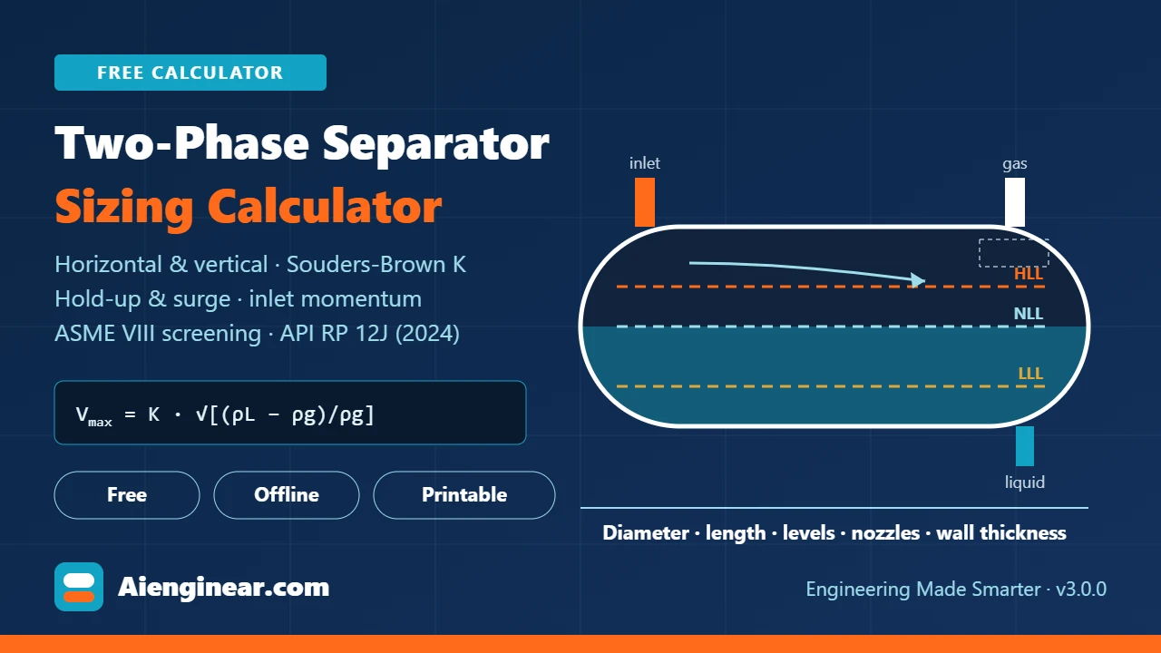
AIENGINEAR CALCULATOR · PROCESS EQUIPMENT
Quick answer: how do you size a two-phase separator?
Size it twice and keep the larger answer. For the gas, limit the velocity through the gas flow area to the Souders-Brown allowable Vmax = K · √[(ρL − ρg) / ρg], where K is set by the mist eliminator (about 0.35 ft/s for a wire-mesh pad at low pressure, derated as pressure rises). For the liquid, provide hold-up volume between LLL and NLL equal to the liquid rate times the hold-up time (typically 1 to 3 minutes for oil), plus surge volume between NLL and HLL. A vertical vessel takes its diameter from the gas area and its height from the liquid and disengagement stack; a horizontal vessel takes its length from whichever of hold-up, surge or droplet settling needs the most, with L/D kept between about 3 and 5. Then check inlet momentum, nozzle sizes and wall thickness. The calculator below does all of this, rounds to fabrication sizes and tells you which criterion governs.
Key takeaways
- A separator has two independent jobs, gas capacity and liquid capacity. Whichever needs the bigger vessel governs, and knowing which one it is tells you what to change.
- The process design reference is now API RP 12J, 9th edition (September 2024), Process Design of Oil and Gas Separators and Scrubbers, a recommended practice that succeeds the long-running API Specification 12J.
- Published K-factors are starting points. Demister capacity is supplier-specific, so final K should come from the internals vendor, derated for pressure, foaming and fouling.
- Inlet momentum limits are stated in pascals: roughly 1,000 Pa for a plain pipe inlet, 1,500 Pa for a half-open pipe, around 6,000 Pa for a vane inlet. Version 3.0.0 of this calculator corrects an earlier unit error on these limits.
- Screening wall thickness uses ASME VIII-1 UG-27 and UG-32 with SA-516 Grade 70 at 20,000 psi, the current ASME II-D value, not the pre-1999 figure of 17,500 psi still found in old spreadsheets.
- Everything runs in your browser. No inputs leave your device and nothing is stored on a server.
How to use the calculator
The tool is laid out as a sequence of tabs, but the sidebar updates live, so you can watch the vessel change as you type.
- Choose the orientation, demister and inlet device. These three choices set the K-factor, the vertical height allowances and the inlet momentum limit. If you are not sure which orientation suits the duty, start with either; the orientation wizard on tab 4 will tell you if the other looks better.
- Enter flows at standard conditions and pressure and temperature at operating conditions. Gas can be entered in MMSCFD, Sm³/d, Sm³/h or Nm³/h; the reference conditions for each are printed under the field.
- Set Z. Type a value from your simulation, or let the tool estimate it with the Sutton pseudo-critical correlation and the Dranchuk-Abou-Kassem equation of state. A warning appears if the reduced conditions fall outside the range where DAK is reliable.
- Review the K-factor. The default is a typical value for the demister you chose, derated for pressure. If you have a vendor rating, switch to manual K and enter it. Apply a service factor for foaming or fouling.
- Enter hold-up and surge times, plus any extra slug volume. For horizontal vessels, set LLL, NLL and HLL as fractions of the diameter.
- Read the Results tab and the governing criterion. Then work through tab 4 (inlet momentum, nozzle sizes, droplet settling, advisor) and tab 5 (design pressure, wall thickness, weights).
- Save the case and try the alternative. The Compare tab holds up to six cases side by side, which is the fastest way to settle vertical against horizontal or mesh pad against vane pack.
- Export. Print a branded PDF report, or download Excel, CSV or JSON. The Report tab also runs a built-in self-test against hand-checked values.
Practical tip
Run the design case and the worst slug or upset case separately. A separator that is comfortably gas-governed at design flow can become liquid-governed the moment a pipeline slug arrives. The extra slug volume field adds directly to the surge band, so you can see immediately whether the vessel still fits.
What is a two-phase separator?
A two-phase separator is a pressure vessel that splits a mixed stream into a gas phase and a single liquid phase. It is the first piece of equipment downstream of most wellheads, the suction scrubber in front of every compressor, and the knock-out drum ahead of fuel gas systems and flares. The liquid may be oil, condensate, water or a mixture handled as one phase; once water must also be separated from oil, the vessel becomes a three-phase separator and needs an additional settling criterion.
Every separator, whatever its shape, has the same four functional zones. The inlet zone takes the momentum out of the incoming stream and does the bulk split, ideally without shattering the liquid into fine mist. The gravity settling zone gives the gas a slow enough path that droplets fall out. The mist extraction zone, usually a wire-mesh pad, vane pack or bank of small cyclones, captures the fine droplets gravity cannot. The liquid collection zone holds the liquid long enough for entrained gas to escape and for the level controller to do its job without hunting.
The two sizing criteria
The single idea that makes separator sizing manageable is that gas capacity and liquid capacity are almost independent. Gas capacity depends on the cross-section available to the gas and on how fast droplets fall; liquid capacity depends on the volume held between the level set-points. You can satisfy each on its own, and the vessel you buy is the one that satisfies both.
That is why the calculator always reports a governing criterion. If gas governs, a better demister (higher K) shrinks the vessel and extra hold-up time costs almost nothing. If liquid governs, the demister choice barely matters and the levers are hold-up time, surge allowance, level settings and orientation. Engineers who skip this step often spend weeks optimising the wrong variable.
In practice, high gas-to-liquid ratio duties (compressor scrubbers, fuel gas knock-outs, gas well separators) tend to be gas-governed and vertical, while oil production separators with modest gas-oil ratios tend to be liquid-governed and horizontal. Worked example 1 below is a useful warning: a gas scrubber that looks gas-governed on paper turns out to be set by the liquid height once realistic level spacing is added.
Gas density and compressibility
Every gas-side number depends on gas density at operating conditions, so it is worth getting right. The calculator uses the real-gas law:
P and T are absolute. The common slip is entering gauge pressure where absolute is needed; at 100 psig that is a 13 % error in density, and a 7 % error in the allowable velocity. The calculator converts gauge units to absolute automatically.
When no simulation Z is available, the tool estimates the pseudo-critical properties from gas gravity with the Sutton correlation and solves the Dranchuk-Abou-Kassem equation iteratively. For a 0.65 gravity gas at 1,000 psig and 100 °F it returns Z = 0.869, against the 0.85 often assumed in hand calculations. That 2 % difference flows straight into the gas volume and the vessel diameter, which is why a single consistent Z source matters more than the third decimal.
The actual gas flow at operating conditions follows from the standard flow:
Souders-Brown equation and K-factor
Souders and Brown published their capacity relation in 1934 for distillation columns, and it has been the backbone of separator gas sizing ever since. It balances the weight of a droplet against the drag of the gas rising past it and folds the droplet size, drag coefficient and geometry into a single empirical constant, K:
For a vertical vessel the gas area is the whole cross-section. For a horizontal vessel it is the segment above the high liquid level, which is why raising HLL in a horizontal vessel quietly reduces its gas capacity.
K is not a property of the fluid. It is a property of the device that has to catch the droplets, and it is the single most influential number in gas-governed sizing. The values below are typical published ranges. Demister capacity is supplier-specific, so treat them as screening values and replace them with the vendor’s rated K before committing to a vessel size.
Typical Souders-Brown K-factors by mist eliminator
Aienginear Table 1
Typical Souders-Brown K-factors by mist eliminator
Screening values at low pressure, before pressure derating and service factors
| Mist eliminator | Typical K, ft/s | Calculator default | Droplets removed | Notes |
|---|---|---|---|---|
| None (gravity only) | 0.10 to 0.20 | 0.15 | ~100 to 150 µm+ | Knock-out drums and flare drums; large vessel for the gas rate |
| Wire-mesh pad | 0.18 to 0.35 | 0.35 | ~10 µm+ | Most common choice; sensitive to fouling, waxy service and liquid loading |
| Vane pack | 0.30 to 0.65 | 0.50 | ~20 to 40 µm+ | Tolerates fouling and higher liquid load; orientation-specific ratings |
| Demisting cyclones | 0.50 to 1.0+ | 0.60 | ~10 µm+ | High capacity and good at high pressure; rating is strictly vendor-specific |
Two corrections are applied on top of the base K. First, pressure: capacity of mesh pads falls as pressure rises, because surface tension drops and the gas density approaches the liquid density. A widely used screening rule reduces K by 0.01 ft/s for every 100 psi above 100 psig. The calculator applies this rule to the typical K values, with a floor at half the base value, and you can switch it off when you enter a vendor K that already includes pressure. Second, a service factor of 0.7 to 0.9 for foaming or fouling duties.
Effect of pressure derating on a wire-mesh pad
Aienginear Table 2
Effect of pressure derating on a wire-mesh pad
Base K = 0.35 ft/s, reduced by 0.01 ft/s per 100 psi above 100 psig
| Operating pressure, psig | Operating pressure, barg | Derated K, ft/s | K as % of base | Implication |
|---|---|---|---|---|
| 100 | 6.9 | 0.350 | 100 % | No derating at or below 100 psig |
| 250 | 17.2 | 0.335 | 96 % | Negligible effect |
| 500 | 34.5 | 0.310 | 89 % | Gas area grows by about 13 % |
| 1,000 | 68.9 | 0.260 | 74 % | Gas area grows by about 35 %; diameter by about 16 % |
| 1,500 | 103.4 | 0.210 | 60 % | Consider vane or cyclonic internals rated for high pressure |
| 2,000 | 137.9 | 0.175 | 50 % | Floor applied; vendor data essential |
K is a capacity limit, not a target
Running a mesh pad well below its rated K is not always better. At very low gas velocity, small droplets pass straight through a mesh pad without impacting the wires. Most suppliers quote a turndown of about 30 % of design velocity. If the vessel has a large turndown range, check the pad’s performance at minimum flow as well as maximum.
Droplet settling
The Souders-Brown check hides a droplet calculation inside K. The calculator also performs that calculation explicitly, because it is what decides whether a vessel without a demister works, and it sets the effective length of a horizontal separator. The terminal velocity of a droplet of diameter dp is:
The drag coefficient depends on the droplet Reynolds number, which depends on Vt, so the tool iterates to a converged solution. The table shows how strongly the result depends on droplet size and on pressure.
Terminal settling velocity of liquid droplets in natural gas
Aienginear Table 3
Terminal settling velocity of liquid droplets in natural gas
0.65 gravity gas; oil 50 to 53 lb/ft³; computed with the drag correlation used in the calculator
| Droplet, µm | Vt at 150 psig, ft/s | Vt at 1,000 psig, ft/s | What it means |
|---|---|---|---|
| 50 | 0.27 | 0.16 | Too slow for gravity alone at practical vessel sizes; needs a demister |
| 100 | 0.76 | 0.38 | Upper end of typical gravity-section design |
| 150 | 1.25 | 0.57 | Common design droplet for the gravity section ahead of a demister |
| 300 | 2.42 | 0.98 | Coarse knock-out duty |
| 500 | 3.58 | 1.37 | Flare knock-out drum design droplet range in some practices |
Notice that a 150 µm droplet falls less than half as fast at 1,000 psig as at 150 psig. Higher pressure means denser gas, more drag and less density difference to drive settling. This is the physical reason behind the K derating in Table 2.
Hold-up, surge and liquid levels
The liquid side of the vessel is defined by three control levels. Below the low liquid level (LLL) sits a minimum depth that keeps gas from blowing out of the liquid outlet. Between LLL and the normal liquid level (NLL) sits the hold-up volume, sized from the liquid rate and the time the liquid needs to release its gas and to give the level controller room to work. Between NLL and the high liquid level (HLL) sits the surge volume, which absorbs slugs and upsets without tripping the vessel or flooding the demister. Above HLL is the gas space.
The calculator sizes hold-up and surge as separate bands. Earlier versions, and many spreadsheets, lumped them into one volume, which lets a generous surge band hide an undersized hold-up band. Keeping them separate means each requirement is met in its own place, which is how the level instrumentation will actually see them.
Typical liquid hold-up times for two-phase service
Aienginear Table 4
Typical liquid hold-up times for two-phase service
Screening guidance; project specifications and operating experience take precedence
| Service | Hold-up time | Comment |
|---|---|---|
| Light oil or condensate, above about 35 °API | 1 to 2 min | Gas releases quickly; level control usually sets the minimum |
| Medium crude, about 20 to 35 °API | 2 to 3 min | A sensible default for production separators |
| Heavy crude, below about 20 °API | 3 to 5 min | Higher viscosity slows bubble rise |
| Foaming crude | 5 min or more | Combine with a K service factor and consider antifoam or internals |
| Compressor suction scrubber | Level span, often < 1 min | Usually set by instrument span and slug volume rather than degassing |
| Flare or vent knock-out drum | Per relief scenario | Sized for the liquid released in the governing relief case, typically 20 to 30 min of rainout |
Sizing a vertical separator
A vertical vessel’s diameter is set by gas capacity: the whole cross-section is available to the rising gas, so D = √(4Qa/πVmax). The height is then built up as a stack of allowances. The calculator follows the widely used approach published by Svrcek and Monnery, with values chosen for practical level instrumentation and inlet disengagement.
Vertical separator height allowances used by the calculator
Aienginear Table 5
Vertical separator height allowances used by the calculator
Tangent-to-tangent height, from the bottom up; dn is the inlet nozzle ID
| Section | Allowance | Purpose |
|---|---|---|
| Bottom tangent to LLL | 15 in default (editable) | Keeps vortex and gas carry-under away from the liquid outlet |
| LLL to NLL (hold-up) | Vhold / A, minimum 6 in | Degassing and level control |
| NLL to HLL (surge) | Vsurge / A, minimum 6 in | Slugs and upsets |
| HLL to inlet nozzle centreline | 12 in + dn/2 with an inlet device; 24 in + dn/2 without | Stops the inlet jet striking the liquid surface |
| Inlet centreline to demister | Larger of 0.5D and 24 in + dn/2 (36 in without a demister) | Gravity disengagement space |
| Demister thickness | Mesh 6 in, vane 12 in, cyclones 18 in | Internals envelope; confirm with the supplier |
| Demister to top tangent | 12 in with a demister, 6 in without | Even gas distribution to the outlet |
If the resulting H/D exceeds the maximum you set (4 by default), the diameter is stepped up and the stack is recalculated. A larger diameter shortens the liquid bands, so the vessel becomes squatter. When that happens the governing criterion changes from gas capacity to liquid height, which is a strong hint that a horizontal vessel deserves a look.
Sizing a horizontal separator
In a horizontal vessel the gas flows along the vessel above the liquid, and droplets settle across its path. The length is set by whichever of three requirements needs the most:
- Hold-up length: the length at which the segment between LLL and NLL holds the hold-up volume.
- Surge length: the length at which the segment between NLL and HLL holds the surge volume.
- Droplet settling length: the length at which the gas residence time equals the time for the design droplet to fall from the top of the vessel through the gas space to HLL, Leff = Vg · hgas / Vt.
The diameter starts at the minimum needed to keep the gas velocity above HLL below Vmax. The seam-to-seam length is taken as the larger of Leff + D (room for the inlet and outlet zones) and 4/3 × Leff. If L/D exceeds the limit, the diameter is stepped up in 6-inch increments until it fits. With rounding switched on, both D and L land on 6-inch (150 mm) steps that a fabricator will recognise.
Most horizontal two-phase separators end up with L/D between 3 and 5. Below 3, the gas probably governs and a vertical vessel may be cheaper; above 5, the vessel becomes long, harder to support and more sensitive to wave motion on the liquid surface.
Inlet momentum and inlet devices
The inlet is where most separators are won or lost. A high-momentum feed hitting a flat plate atomises liquid into droplets far smaller than the gravity section was designed for, and the demister is then asked to do the separator’s job. The usual check is the momentum flux of the mixture in the inlet nozzle:
Typical inlet momentum limits by inlet device
Aienginear Table 6
Typical inlet momentum limits by inlet device
Indicative industry values; the inlet device supplier’s rating governs
| Inlet device | Typical limit, Pa | Equivalent, lb/(ft·s²) | Comment |
|---|---|---|---|
| Plain pipe, no device | about 1,000 | about 670 | Low-momentum feeds only |
| Half-open pipe or simple diverter | about 1,500 | about 1,000 | Common in older and small vessels |
| Vane-type inlet | about 6,000 (up to ~9,000) | about 4,000 | Distributes flow along the vessel; the usual upgrade |
| Inlet cyclones | 10,000 and above | 6,700 and above | Vendor-rated; also helps with foaming feeds |
Correction in v3.0.0
Version 2 of this calculator compared the momentum flux in lb/(ft·s²) against limits of 1,500 and 9,000 that are normally quoted in pascals. Because 1 lb/(ft·s²) is about 1.49 Pa, that check was roughly 50 % too lenient. Version 3.0.0 computes momentum in pascals, shows the US equivalent beside it, and also back-calculates the smallest inlet nozzle that meets the limit for the device you selected.
Outlet nozzle sizing
The calculator gives minimum diameters for the gas and liquid outlets as well as the inlet. For the gas outlet it limits ρgv² to about 3,750 Pa, a common criterion that keeps re-entrainment and noise down and avoids a large pressure drop leaving the demister. For the liquid outlet it limits velocity to about 1 m/s (3.3 ft/s) so that the outlet does not pull a vortex and carry gas under. Use these as minimums: the final size is often set by the downstream line, the control valve or a vortex breaker arrangement.
Wall thickness and weight
A separator is a pressure vessel, and its size drives cost mainly through wall thickness. Tab 5 of the calculator gives a screening thickness to ASME BPVC Section VIII Division 1 so that you can compare vertical and horizontal options on weight, not just volume.
- Design pressure defaults to the larger of 1.10 × operating pressure and operating pressure + 25 psi, a common practice that leaves margin for the relief valve set point. Enter your own value if the project defines it.
- Allowable stress defaults to 20,000 psi for SA-516 Grade 70, the ASME Section II Part D value up to 650 °F. Values of 17,500 psi found in older tools date from before the 1999 change in design margin.
- Thickness is rounded up to the next 1/16 in and to your minimum plate thickness. The tool warns if pressure exceeds 0.385SE, where the thin-shell formula stops applying.
- Empty, operating and flooded weights are given with an allowance for nozzles and internals. Flooded weight matters for foundations and for hydrotesting a vessel installed on a structure.
Use the ASME VIII pressure vessel calculator for the full mechanical design: MAWP, nozzle reinforcement, external pressure and hydrotest.
Worked example 1: vertical gas scrubber
Duty: 10 MMSCFD of 0.65 gravity gas with 2,000 BPD of 50 lb/ft³ oil at 1,000 psig and 100 °F. Z = 0.85, wire-mesh pad, half-open pipe inlet with a 6-inch nozzle, 2 minutes hold-up and 1 minute surge, maximum H/D of 4. Load it in the calculator with the Example 1 button.
Example 1 step-by-step results
Aienginear Table 7
Example 1 step-by-step results: vertical scrubber
Hand calculation reproduced by the calculator’s built-in self-test
| Step | Working | Result |
|---|---|---|
| 1. Gas density | 1,014.7 × 18.83 / (0.85 × 10.7316 × 559.67) | 3.742 lb/ft³ |
| 2. K-factor | 0.35 − 0.01 × (1,000 − 100)/100 | 0.260 ft/s |
| 3. Allowable velocity | 0.260 × √[(50 − 3.742)/3.742] | 0.914 ft/s |
| 4. Actual gas flow | 115.74 scf/s × (14.696/1,014.7) × (559.67/519.67) × 0.85 | 1.535 ft³/s |
| 5. Diameter for gas alone | √(4 × 1.535 / (π × 0.914)) | 1.46 ft (17.5 in) |
| 6. Liquid volumes | 0.1300 ft³/s × 120 s and × 60 s | 15.6 and 7.8 ft³ |
| 7. Try D = 2.5 ft | Stack 1.25 + 3.18 + 1.59 + 1.25 + 2.25 + 0.5 + 1.0 = 11.0 ft | H/D 4.41, too slender |
| 8. Select D = 3.0 ft | Stack 1.25 + 2.21 + 1.10 + 1.25 + 2.25 + 0.5 + 1.0 = 9.56 ft, rounded up | 36 in × 10.0 ft T/T |
| 9. Gas velocity check | 1.535 / 7.07 ft² | 0.217 ft/s, 24 % of Vmax |
| 10. Inlet momentum | 6 in nozzle, mixture 7.35 lb/ft³ at 8.48 ft/s | 786 Pa < 1,500 Pa |
| 11. Wall thickness | Design 1,100 psig, S = 20,000 psi, E = 0.85, CA 1/8 in | Shell 1-3/8 in, heads 1-5/16 in |
| 12. Weights | Shell and heads plus 10 % allowance | Empty about 7,300 lb; flooded about 12,100 lb |
The lesson is in step 7. Gas alone needs only an 18-inch vessel, but at that diameter the liquid bands are several feet tall and the vessel becomes a pipe. Raising the diameter to 36 inches brings H/D to 3.3. The gas velocity is now only a quarter of the allowable, so the mesh pad will be lightly loaded; check its turndown with the supplier. If the 1,000 psig wall thickness makes this vessel expensive, try a horizontal vessel or a smaller diameter with a higher H/D limit and compare the weights on the Compare tab.
Worked example 2: horizontal production separator
Duty: 5 MMSCFD of 0.65 gravity gas (Z = 0.97) with 20,000 BPD of 53 lb/ft³ crude at 150 psig and 100 °F. Wire-mesh pad, vane inlet with a 12-inch nozzle, 3 minutes hold-up and 1 minute surge, levels at 20, 50 and 70 % of D, maximum L/D of 4. Load it with the Example 2 button.
Example 2 results
Aienginear Table 8
Example 2 results: horizontal production separator
Liquid-governed duty with a low gas-oil ratio of 250 scf/bbl
| Quantity | Value | Comment |
|---|---|---|
| Gas density / K / Vmax | 0.532 lb/ft³ / 0.345 / 3.43 ft/s | Low pressure, so K is barely derated |
| Actual gas flow / liquid flow | 5.39 / 1.30 ft³/s | Liquid is a quarter of the gas volume |
| Hold-up / surge volume | 233.9 / 78.0 ft³ | 3 min and 1 min |
| Minimum diameter for gas | 2.82 ft | Gas needs very little |
| Length needed: hold-up / surge / droplet at D = 7 ft | 17.0 / 8.2 / 0.9 ft | Hold-up governs by a wide margin |
| Selected vessel | 84 in ID × 24 ft S/S | L/D 3.43 |
| Hold-up / surge provided | 3.0 / 2.1 min | Surge band has spare capacity for slugs |
| Gas velocity | 0.56 ft/s, 16 % of Vmax | Gas side is lightly loaded |
| Inlet momentum, 12 in nozzle | 1,159 Pa | Well within about 6,000 Pa for a vane inlet |
| Liquid outlet minimum ID | 8.5 in | At 1 m/s; a 10 in outlet is the likely choice |
| Shell / head thickness | 9/16 in / 9/16 in | Design 175 psig |
| Empty / operating / flooded weight | 16,200 / 43,000 / 79,400 lb | Operating weight is liquid-dominated |
Switch the same duty to vertical and the calculator returns a 66-inch by 20.5-foot vessel that is lighter on paper. It is still the wrong choice for most production service. The vertical vessel’s liquid surface is about 24 ft² against roughly 120 ft² in the horizontal one, so gas has far less interface to escape through; its high level sits more than 14 feet above the bottom, which complicates level instrumentation and access; and a slug raises its level several times faster. Weight is one input to the decision, not the decision.
Horizontal or vertical?
Horizontal and vertical separators compared
Aienginear Table 9
Horizontal and vertical separators compared
Selection guidance for two-phase gas-liquid service
| Factor | Horizontal | Vertical |
|---|---|---|
| Best when | Liquid governs: low gas-liquid ratio, high liquid load | Gas governs: high gas-liquid ratio, small liquid load |
| Typical gas-liquid ratio | Below about 4,000 scf/bbl | Above about 20,000 scf/bbl; either in between |
| Liquid surface for degassing | Large | Small |
| Slug and surge handling | Good: level rises slowly | Poorer: level rises quickly |
| Plot space | Larger footprint | Small footprint; good offshore and on skids |
| Sand and solids | Harder to remove; needs sand jetting | Easier: solids collect in a cone or dished bottom |
| Level control | Small level span for a given volume can make control sensitive | Wide level span, easy to control |
| Typical L/D or H/D | 3 to 5 | 2 to 4 |
| Three-phase upgrade | Natural choice | Possible but less common |
Common sizing mistakes
- Using a K-factor without pressure derating. At 1,000 psig the typical mesh pad K falls by about a quarter. Ignoring it leaves the gas flow area roughly 26 % too small.
- Treating a textbook K as a guarantee. Demister performance is supplier-specific. Use published values to screen and the vendor’s rating to design.
- Gauge pressure in the gas law. Always absolute.
- Lumping hold-up and surge together. The total volume can look fine while the hold-up band between LLL and NLL is too small.
- Raising HLL in a horizontal vessel to gain liquid volume without rechecking the gas area above it.
- Ignoring the inlet. An undersized nozzle with a plain inlet can halve real separation performance regardless of the vessel size.
- Sizing only at design flow. Check maximum flow for gas capacity, slugs for surge, and minimum flow for demister turndown.
- Forgetting the outlet nozzles. An undersized liquid outlet vortexes and carries gas under; an undersized gas outlet re-entrains liquid off the demister.
- Using old allowable stresses. 17,500 psi for SA-516-70 is a pre-1999 value and overstates wall thickness by about 14 %.
Troubleshooting
Separator troubleshooting guide
Aienginear Table 10
Separator troubleshooting guide
Operating symptoms, likely causes and first checks
| Symptom | Likely causes | First checks |
|---|---|---|
| Liquid carry-over in the gas | Gas rate above design, demister damaged or fouled, HLL too high, inlet momentum too high, foaming | Demister differential pressure, actual rate against Vmax, level trend, inlet ρv² |
| Gas carry-under in the liquid | Hold-up too short, vortex at the outlet, LLL too low, foaming | Actual hold-up time, vortex breaker, outlet velocity |
| High-level trips on slugs | Surge band too small, level controller too slow | Slug volume against NLL-to-HLL volume; controller tuning |
| Rising demister Δp | Wax, scale, sand or hydrates in the pad | Pad inspection; consider a vane pack for fouling service |
| Erratic level control | Small level span in a horizontal vessel, wave action, foam | Level span in millimetres; stilling well; level instrument type |
| Carry-over only at low flow | Mesh pad below its minimum effective velocity | Supplier turndown data; consider a combined mesh-vane design |
What is new in v3.0.0
- Inlet momentum corrected to pascals, with limits for four inlet device types and a minimum-nozzle back-calculation.
- Hold-up and surge sized as separate level bands, plus an extra slug volume input.
- Horizontal length from hold-up, surge or droplet settling, whichever governs, with seam-to-seam length from Leff.
- Vertical height stack with inlet, disengagement and demister allowances, and automatic diameter increase when H/D is exceeded.
- Fabrication rounding to 6 in (150 mm) steps for diameter and length.
- ASME VIII-1 screening with design pressure margin, 2:1 head thickness, S = 20,000 psi for SA-516-70, hydrotest pressure and empty, operating and flooded weights.
- Gas and liquid outlet nozzle minimums, a K service factor for foaming, and DAK range warnings.
- Case comparison, branded print report, Excel, CSV, JSON and shareable links, with a built-in self-test.
- References updated to API RP 12J, 9th edition (2024) and the ASME BPVC 2025 edition.
How this calculator compares
Aienginear Two-Phase Separator Calculator vs typical free online tools
Aienginear Table 11
Aienginear Two-Phase Separator Calculator vs typical free online tools
What most free separator calculators do, and what this one adds
| Capability | Typical free calculator | Aienginear calculator v3.0.0 |
|---|---|---|
| Souders-Brown gas capacity | Yes | Yes, with demister-specific K, pressure derating and service factor |
| Horizontal and vertical in one tool | Often one or the other | Both, with an orientation wizard and side-by-side case comparison |
| Separate hold-up and surge bands | Rarely | Yes, plus extra slug volume |
| Explicit droplet settling with iterated drag | Seldom | Yes; sets horizontal effective length |
| Inlet momentum in correct units | Often missing or unit-ambiguous | Pascals, four device types, minimum nozzle back-calculation |
| Gas and liquid outlet nozzle minimums | No | Yes |
| Compressibility from gas gravity | Sometimes | Sutton + DAK with validity warning |
| Fabrication-size rounding | No | 6 in (150 mm) steps |
| ASME VIII-1 screening thickness and weights | No | Shell, 2:1 heads, hydrotest, empty, operating and flooded weight |
| Live dimensioned sketch | Rarely | Yes, printable |
| Printable engineering report and Excel export | No | Branded PDF report, Excel, CSV, JSON, share link |
| Built-in self-test | No | Yes, against hand-checked values |
| US and metric units | Often one system | Both, switchable at any time |
| Privacy and cost | Varies; some need sign-up | Free, no registration, runs entirely in the browser |
Standards and references
Governing documents and what each is used for
Aienginear Table 12
Governing documents and what each is used for
Status checked October 2026; always confirm the edition named in your project specification
| Document | Scope | Role in this calculator |
|---|---|---|
| API RP 12J, 9th edition (2024) | Process design of oil and gas separators and scrubbers | Primary process design reference: separation principles, sizing approach, internals and momentum criteria |
| API Spec 12J, 8th edition (2008, reaffirmed) | Earlier specification for oil and gas separators | Historic source of retention-time guidance still quoted in many company standards |
| GPSA Engineering Data Book, Section 7 | Separators and filters | K-factor ranges, pressure derating rule and droplet drag correlation |
| ASME BPVC Section VIII Division 1 (2025) | Rules for construction of pressure vessels | UG-27 shell, UG-32 head, UG-99 hydrotest screening |
| ASME BPVC Section II Part D (2025) | Material properties | Allowable stress for SA-516 Grade 70 and SA-240 stainless |
| API RP 14E | Design of offshore production platform piping | Context for nozzle and line velocities |
| API Std 521 | Pressure-relieving and depressuring systems | Flare knock-out drum sizing, which this tool does not replace |
| Souders and Brown (1934), Ind. Eng. Chem. | Original capacity correlation | Allowable gas velocity |
| Svrcek and Monnery (1993), Chem. Eng. Prog. | Two-phase separator design limits | Vertical height allowances and level practice |
| Arnold and Stewart, Surface Production Operations | Production facility design | Horizontal effective length and seam-to-seam practice |
| Dranchuk and Abou-Kassem (1975); Sutton (1985) | Gas compressibility | Z-factor estimate from gas gravity |
Assumptions and limitations
- Two-phase only. Oil-water separation, emulsions and three-phase settling are outside scope.
- Steady flow. Slugs are handled as an added surge volume, not by transient simulation. Severe slugging needs a slug catcher study.
- Published K values are typical, not guaranteed. Pressure derating is a screening rule. Use vendor ratings for design and for any high-pressure, foaming or fouling service.
- Gas density uses the real-gas law with a manual or DAK Z. Near the critical point, or for rich gases and sour gases, use Z from an equation of state.
- Vertical allowances and horizontal level fractions are common practice, not code requirements. Company standards may require different values.
- Nozzle criteria are indicative. Final nozzle sizes depend on the internals, the downstream piping and the control valves.
- Mechanical results are screening only. They exclude nozzle reinforcement, external loads, supports, impact testing and the code’s full rules.
- Flare and relief knock-out drums follow API Std 521 relief scenarios and are not designed by this tool.
Quick quiz: test your separator sizing knowledge
1. Gas alone needs an 18-inch vertical vessel, but the calculator selects 36 inches. What governs?
2. Using the screening derating rule, what is a mesh pad K of 0.35 ft/s at 1,000 psig?
3. Where is the surge volume held?
4. A typical inlet momentum limit for a vane-type inlet is about:
5. In a horizontal separator, raising HLL from 70 % to 80 % of D does what to gas capacity?
Related Aienginear calculators and guides
The separator calculator sits in the Aienginear process and pressure integrity families. These are the tools most often used alongside it.
Frequently asked questions
What is a two-phase separator?
A pressure vessel that splits a gas-liquid stream into a gas phase and one liquid phase, using an inlet device for the bulk split, gravity settling, a mist eliminator for fine droplets and a liquid section held under level control. It is sized for gas capacity and liquid capacity, and the larger requirement governs.
How do you size a two-phase separator?
Find the gas flow area from the Souders-Brown allowable velocity, and the liquid volume from the liquid rate times hold-up and surge times. For a vertical vessel the gas sets the diameter and the liquid sets the height; for a horizontal vessel the liquid or droplet settling usually sets the length. Choose the diameter that keeps L/D between about 3 and 5, then check inlet momentum, nozzles and wall thickness.
What is the Souders-Brown equation?
Vmax = K · √[(ρL − ρg)/ρg]. It gives the maximum gas velocity at which liquid droplets still separate. K is an empirical capacity factor set mainly by the mist eliminator. Dividing the actual gas flow by Vmax gives the minimum gas flow area.
What K-factor should I use?
Typical ranges are 0.10 to 0.20 ft/s with no demister, 0.18 to 0.35 for a wire-mesh pad, 0.30 to 0.65 for a vane pack and 0.5 to 1.0 or more for demisting cyclones. Derate for pressure above about 100 psig and for foaming or fouling, and replace the typical value with the supplier’s rating for final design.
Which standard covers separator sizing?
API RP 12J, 9th edition, published in September 2024 as Process Design of Oil and Gas Separators and Scrubbers, is the current API document. It succeeds API Specification 12J. The GPSA Engineering Data Book, Section 7, is the other common reference. The vessel itself is designed to ASME BPVC Section VIII.
What retention time should I use?
For two-phase oil service, 1 to 3 minutes of hold-up between LLL and NLL is typical, longer for heavy or foaming crude. Add a surge allowance between NLL and HLL for slugs, often 1 to 2 minutes or a defined slug volume. Your project specification takes precedence.
What are LLL, NLL and HLL?
Low, normal and high liquid levels. Hold-up volume sits between LLL and NLL, surge volume between NLL and HLL, and the gas space above HLL. Alarms and trips (LALL, LAHH) sit beyond LLL and HLL.
Should I choose a horizontal or a vertical separator?
Choose horizontal when liquid governs: low gas-liquid ratio, large liquid volume, slugging or foaming. Choose vertical when gas governs: high gas-liquid ratio, small liquid volume, tight plot space or solids. In between, size both, save each as a case and compare weight, footprint and operability.
What inlet momentum limit applies?
Typical values are about 1,000 Pa for a plain pipe inlet, 1,500 Pa for a half-open pipe or diverter, about 6,000 Pa for a vane inlet and 10,000 Pa or more for inlet cyclones, always subject to the supplier’s rating. Make sure your calculation and the limit use the same units.
Why does the calculator make my vessel bigger than the gas needs?
Because liquid governs. The liquid bands would make the vessel too slender at the gas-only diameter, so the diameter is raised until L/D or H/D is within your limit. The governing criterion shown on the Results tab tells you when this has happened.
Can I use the calculator for compressor suction scrubbers?
Yes, for screening. Use a vertical vessel with a high-efficiency demister and short hold-up, and check the result against the compressor vendor’s liquid carry-over requirement and the scrubber internals supplier’s rating.
Can it design flare knock-out drums?
No. Flare and vent knock-out drums are sized from the relief scenarios and droplet criteria in API Std 521. The settling relations are similar, but the design cases are different.
Does it handle three-phase separators?
No. Three-phase separation adds oil-water settling and interface level control. Version 3.0.0 is limited to two-phase gas-liquid service.
Is this calculator suitable for final design?
It is a preliminary engineering and design-support tool for concept, FEED and checking. Final design needs vendor-rated internals, project specifications, process simulation data and full ASME VIII mechanical design by a qualified engineer.
Is my data sent anywhere?
No. The calculator is a single file that runs entirely in your browser. Inputs are kept only in your own browser storage for convenience, and nothing is sent to a server.
Disclaimer
This calculator and article support preliminary engineering, screening, education and design. Souders-Brown K values, pressure derating, hold-up times, level allowances, inlet momentum limits and nozzle criteria are typical published or industry values, not guarantees. Mechanical results are screening estimates to ASME VIII-1. Results depend entirely on the inputs and stated assumptions and do not replace process simulation, internals vendor data, project specifications, applicable codes or review by a qualified engineer. Always have separator designs reviewed by a competent engineer before purchase, construction or operation.
Aienginear Two-Phase Separator Sizing Calculator · calculator v3.0.0 · article updated 28 October 2026 · standards status checked October 2026 · Published by Aienginear.com, Engineering Made Smarter. Found an error? Tell us.

Written by Muhammad Raza
Founder of Aienginear. Engineering and digital solutions professional with 26+ years managing projects, plant shutdowns and turnarounds in oil & gas, petrochemical and power generation.