
PIPING · FITTINGS · UPDATED OCTOBER 2026
Quick answer: how are pipe fittings dimensioned and specified?
Butt-weld pipe fittings take their size and wall thickness from the pipe they join: NPS (or DN) fixes the outside diameter and the schedule fixes the wall. Their centre-to-end lengths and tolerances come from ASME B16.9-2024 (NPS ½ to 48, now including short-radius elbows). Small-bore forged fittings follow ASME B16.11-2021 and are ordered by class (2000, 3000, 6000 or 9000) and end type (socket-weld or threaded) for NPS ⅛ to 4. Material is chosen to match the pipe: for example A106 Gr B pipe takes A234 WPB wrought fittings and A105 forged fittings; A312 TP316L takes A403 WP316L and A182 F316L.
A fitting that is the right shape but the wrong wall, bevel or grade is still the wrong fitting. Mismatched bores create weld defects, an under-thickness elbow becomes the weakest point in the line, and a carbon steel tee slipped into a low-temperature system can fail by brittle fracture on the first cold start. This guide sets out how fitting dimensions and materials are defined, which standards control them in 2026, and what an inspector should measure before a fitting goes into a live system. If you need a refresher on the fitting families themselves, start with our guide to types of pipe fittings.
Size basics: NPS, DN, OD and schedule
Every butt-weld fitting is described by the same two numbers used for the pipe: a nominal size and a wall thickness designation. Nominal Pipe Size (NPS) is the North American designation in inches; Diameter Nominal (DN) is the metric equivalent used in ISO and EN documents. Neither is a measured diameter. What they do fix is the outside diameter (OD), which is identical for every schedule of a given size. For NPS 14 and larger, the OD in inches equals the NPS number; below NPS 14 it is larger than the nominal figure (NPS 2 has an OD of 60.3 mm, not 50.8 mm).
Because the OD is fixed, a heavier schedule makes the bore smaller. That is why a fitting must be ordered in the same schedule as the pipe: the OD will match regardless, but only the same wall gives a matching bore and a sound weld root.
Aienginear · Table 1
NPS, DN, OD and wall thickness by schedule (mm)
Carbon steel per ASME B36.10M; Sch 10S per ASME B36.19M
| NPS | DN | OD | Sch 10S | STD | Sch 40 | XS | Sch 80 | Sch 160 | XXS |
|---|---|---|---|---|---|---|---|---|---|
| ½ | 15 | 21.3 | 2.11 | 2.77 | 2.77 | 3.73 | 3.73 | 4.78 | 7.47 |
| ¾ | 20 | 26.7 | 2.11 | 2.87 | 2.87 | 3.91 | 3.91 | 5.56 | 7.82 |
| 1 | 25 | 33.4 | 2.77 | 3.38 | 3.38 | 4.55 | 4.55 | 6.35 | 9.09 |
| 1¼ | 32 | 42.2 | 2.77 | 3.56 | 3.56 | 4.85 | 4.85 | 6.35 | 9.70 |
| 1½ | 40 | 48.3 | 2.77 | 3.68 | 3.68 | 5.08 | 5.08 | 7.14 | 10.15 |
| 2 | 50 | 60.3 | 2.77 | 3.91 | 3.91 | 5.54 | 5.54 | 8.74 | 11.07 |
| 2½ | 65 | 73.0 | 3.05 | 5.16 | 5.16 | 7.01 | 7.01 | 9.53 | 14.02 |
| 3 | 80 | 88.9 | 3.05 | 5.49 | 5.49 | 7.62 | 7.62 | 11.13 | 15.24 |
| 4 | 100 | 114.3 | 3.05 | 6.02 | 6.02 | 8.56 | 8.56 | 13.49 | 17.12 |
| 6 | 150 | 168.3 | 3.40 | 7.11 | 7.11 | 10.97 | 10.97 | 18.26 | 21.95 |
| 8 | 200 | 219.1 | 3.76 | 8.18 | 8.18 | 12.70 | 12.70 | 23.01 | 22.23 |
| 10 | 250 | 273.1 | 4.19 | 9.27 | 9.27 | 12.70 | 15.09 | 28.58 | 25.40 |
| 12 | 300 | 323.9 | 4.57 | 9.53 | 10.31 | 12.70 | 17.48 | 33.32 | 25.40 |
| 14 | 350 | 355.6 | 4.78 | 9.53 | 11.13 | 12.70 | 19.05 | 35.71 | – |
| 16 | 400 | 406.4 | 4.78 | 9.53 | 12.70 | 12.70 | 21.44 | 40.49 | – |
| 18 | 450 | 457.0 | 4.78 | 9.53 | 14.27 | 12.70 | 23.83 | 45.24 | – |
| 20 | 500 | 508.0 | 5.54 | 9.53 | 15.09 | 12.70 | 26.19 | 50.01 | – |
| 24 | 600 | 610.0 | 6.35 | 9.53 | 17.48 | 12.70 | 30.96 | 59.54 | – |
Note: STD equals Sch 40 up to NPS 10, and XS equals Sch 80 up to NPS 8. Above those sizes the designations differ, so never treat them as interchangeable. Source basis: ASME B36.10M / B36.19M. © Aienginear.com
Wall thickness, ID matching and weld ends
Forming an elbow or tee stretches the metal on the outside of the bend (the extrados) and on the shoulders of a tee, so local thinning is unavoidable. ASME B16.9 handles this with a simple rule: the wall at any point must be at least 87.5 % of the nominal wall of the pipe schedule ordered. To meet that after forming, manufacturers usually start from heavier feedstock, which is why a fitting can measure thicker than its matching pipe in some places. Extra thickness is acceptable provided the welding ends still match the pipe.
Where the fitting is thicker than the pipe, or where pipe and fitting come from specifications with different bore tolerances, the inside of the thicker part is machined or trimmed with a taper so the bores line up at the weld root. ASME B31.3 limits that internal taper to no steeper than 30°. The welding end itself is prepared to ASME B16.25-2022, shown below.
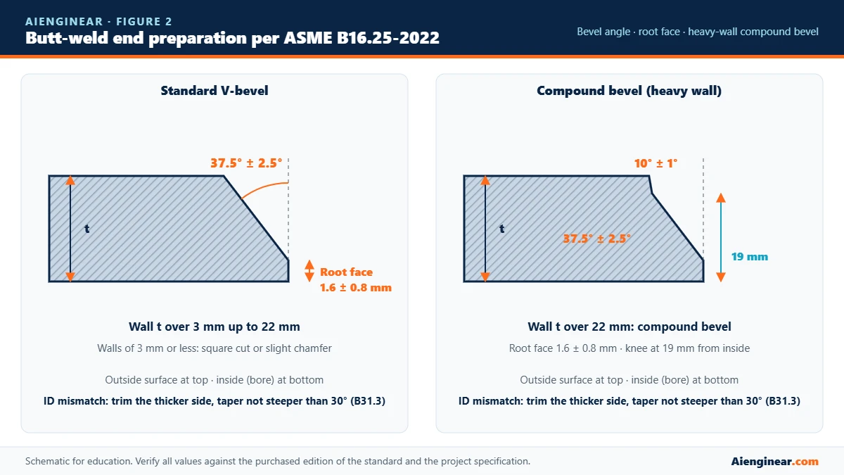
- Wall 3 mm or less: square cut or light chamfer at the manufacturer’s option.
- Wall over 3 mm up to 22 mm: single V-bevel of 37.5° ± 2.5° with a root face of 1.6 ± 0.8 mm.
- Wall over 22 mm: compound bevel, 37.5° ± 2.5° for the first 19 mm from the bore, then 10° ± 1° to the outside surface.
- Different procedure? J-bevels, narrow-gap or automatic-welding preps can be ordered, but they must be shown on the purchase order.
ASME B16.9 butt-weld fitting dimensions
ASME B16.9-2024 sets the overall dimensions, tolerances, ratings, testing and marking for factory-made wrought butt-weld fittings from NPS ½ to NPS 48. One point catches many older specifications: short-radius elbows and returns were moved into B16.9 when the former ASME B16.28 was withdrawn, so a current purchase order should cite B16.9 for both long-radius (LR) and short-radius (SR) elbows. Large-radius pipe bends made by induction bending follow ASME B16.49 instead.
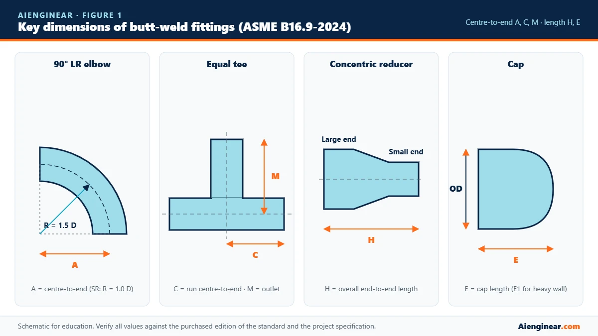
The centre-to-end values below are what piping designers use to lay out spools and what inspectors check with a tape. They are the same for every schedule of a given size.
Aienginear · Table 2
ASME B16.9 centre-to-end and length dimensions (mm)
LR = 1.5D radius, SR = 1.0D radius · see Figure 1 for letters
| NPS | OD | 90° LR elbow A | 45° LR elbow B | 90° SR elbow A | 180° LR return O | Tee C / M | Reducer H | Cap E |
|---|---|---|---|---|---|---|---|---|
| ½ | 21.3 | 38 | 16 | – | 76 | 25 | – | 25 |
| ¾ | 26.7 | 29 | 11 | – | 57 | 29 | 38 | 25 |
| 1 | 33.4 | 38 | 22 | 25 | 76 | 38 | 51 | 38 |
| 1¼ | 42.2 | 48 | 25 | 32 | 95 | 48 | 51 | 38 |
| 1½ | 48.3 | 57 | 29 | 38 | 114 | 57 | 64 | 38 |
| 2 | 60.3 | 76 | 35 | 51 | 152 | 64 | 76 | 38 |
| 2½ | 73.0 | 95 | 44 | 64 | 190 | 76 | 89 | 38 |
| 3 | 88.9 | 114 | 51 | 76 | 229 | 86 | 89 | 51 |
| 4 | 114.3 | 152 | 64 | 102 | 305 | 105 | 102 | 64 |
| 6 | 168.3 | 229 | 95 | 152 | 457 | 143 | 140 | 89 |
| 8 | 219.1 | 305 | 127 | 203 | 610 | 178 | 152 | 102 |
| 10 | 273.1 | 381 | 159 | 254 | 762 | 216 | 178 | 127 |
| 12 | 323.9 | 457 | 190 | 305 | 914 | 254 | 203 | 152 |
| 14 | 355.6 | 533 | 222 | 356 | 1067 | 279 | 330 | 165 |
| 16 | 406.4 | 610 | 254 | 406 | 1219 | 305 | 356 | 178 |
| 18 | 457.0 | 686 | 286 | 457 | 1372 | 343 | 381 | 203 |
| 20 | 508.0 | 762 | 318 | 508 | 1524 | 381 | 508 | 229 |
| 24 | 610.0 | 914 | 381 | 610 | 1829 | 432 | 508 | 267 |
Reducer H is listed against the large-end size. Cap E applies to standard walls; heavier walls use the longer E1 value in B16.9. Values rounded to the nearest mm for quick reference: confirm against the purchased edition before fabrication. © Aienginear.com
Aienginear · Interactive tool
Pipe fitting dimension finder
Pick a size and schedule to get B16.9 dimensions, wall limits, tolerances and bevel type in one place
Data basis: ASME B36.10M / B36.19M walls, ASME B16.9 dimensions and tolerances, ASME B16.25 bevel rules. Quick-reference tool for planning and inspection; the purchased standard and project specification govern.
ASME B16.9 dimensional tolerances
Tolerances are what turn a dimension table into an inspection plan. B16.9 groups them by size band. The values below are the ones most often checked at receiving inspection; the full table in the standard also covers laps, stub ends and other items.
Aienginear · Table 3
Key ASME B16.9 tolerances (mm)
Applies to elbows, tees, reducers, caps and returns
| NPS band | OD at bevel | ID at end | Centre-to-end A, B, C, M | Reducer H | Off-angle Q | Off-plane P |
|---|---|---|---|---|---|---|
| ½ – 2½ | +1.6 / −0.8 | ± 0.8 | ± 2 | ± 2 | 1 | 2 |
| 3 – 3½ | ± 1.6 | ± 1.6 | ± 2 | ± 2 | 1 | 2 |
| 4 | ± 1.6 | ± 1.6 | ± 2 | ± 2 | 1 | 2 |
| 5 – 8 | +2.4 / −1.6 | ± 1.6 | ± 2 | ± 2 | 2 | 4 |
| 10 – 18 | +4.0 / −3.2 | ± 3.2 | ± 2 | ± 2 | 3 | 5 |
| 20 – 24 | +6.4 / −4.8 | ± 4.8 | ± 2 | ± 2 | 4 | 8 |
| 26 – 30 | +6.4 / −4.8 | ± 4.8 | ± 3 | ± 5 | 5 | 10 |
| 32 – 48 | +6.4 / −4.8 | ± 4.8 | ± 5 | ± 5 | 5 | 10 – 13 |
Wall thickness at any point: not less than 87.5 % of nominal. Q = deviation of the end face from square to the fitting axis; P = deviation of the end from its true plane. © Aienginear.com
Forged fittings: ASME B16.11 classes and sizes
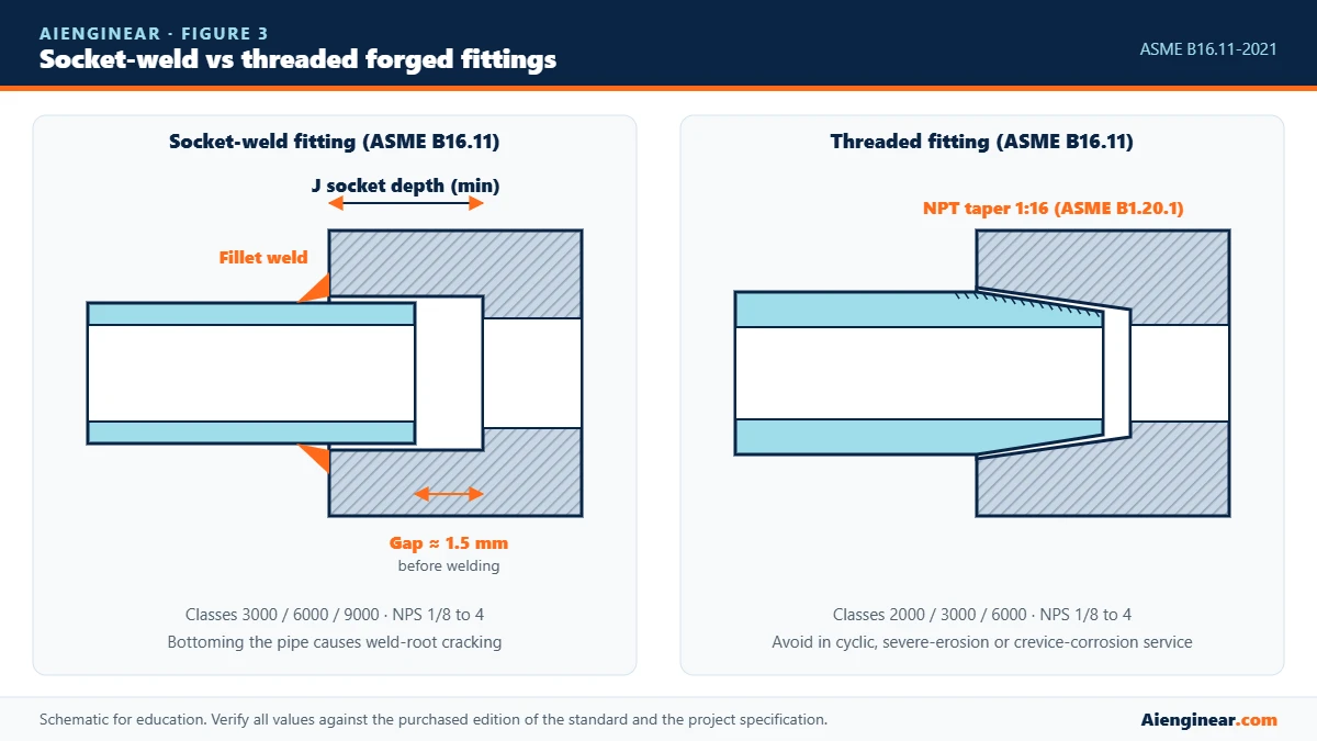
For small-bore lines, vents, drains and instrument connections, forged fittings to ASME B16.11-2021 are the norm. They are machined from forgings or bar and come in two end types: socket-weld (SW), where the pipe slides into a socket and is fillet-welded, and threaded (THD), with NPT taper threads to ASME B1.20.1.
Instead of a schedule, a forged fitting carries a class designation. The class is not a pressure in psi. It tells you which pipe wall the fitting is designed to match, and therefore that the fitting is at least as strong as that pipe. Table 4 shows the pairing.
Aienginear · Table 4
ASME B16.11 class designation, matching pipe and size range
Use the pipe schedule to choose the fitting class
| Class | End type | Matching pipe wall | Size range (NPS) | Typical use |
|---|---|---|---|---|
| 2000 | Threaded | Sch 80 / XS | ⅛ – 4 | Utility, low-pressure water and air |
| 3000 | Threaded | Sch 160 | ⅛ – 4 | General process threaded connections |
| 6000 | Threaded | XXS | ⅛ – 4 | High-pressure threaded service |
| 3000 | Socket-weld | Sch 80 / XS | ⅛ – 4 | Most process small-bore piping |
| 6000 | Socket-weld | Sch 160 | ⅛ – 2 | High pressure, steam, hydrocarbon |
| 9000 | Socket-weld | XXS | ½ – 2 | Very high pressure, heavy-wall lines |
The same class number pairs with a heavier pipe for threaded ends because the threads remove wall. A thinner pipe than the matching schedule can be used; the joint rating is then limited by the pipe. © Aienginear.com
Aienginear · Table 5
Socket-weld fittings: approximate socket bore and minimum socket depth (mm)
ASME B16.11 basis · bore suits the pipe OD in Table 1
| NPS | Pipe OD | Socket bore B (approx.) | Socket depth J (min) | Pipe insertion before gap |
|---|---|---|---|---|
| ½ | 21.3 | 21.9 | 10 | Insert to bottom, then withdraw ≈ 1.5 |
| ¾ | 26.7 | 27.3 | 13 | Insert to bottom, then withdraw ≈ 1.5 |
| 1 | 33.4 | 34.0 | 13 | Insert to bottom, then withdraw ≈ 1.5 |
| 1¼ | 42.2 | 42.8 | 13 | Insert to bottom, then withdraw ≈ 1.5 |
| 1½ | 48.3 | 48.9 | 13 | Insert to bottom, then withdraw ≈ 1.5 |
| 2 | 60.3 | 61.2 | 16 | Insert to bottom, then withdraw ≈ 1.5 |
| 2½ | 73.0 | 73.9 | 16 | Insert to bottom, then withdraw ≈ 1.5 |
| 3 | 88.9 | 89.9 | 16 | Insert to bottom, then withdraw ≈ 1.5 |
| 4 | 114.3 | 115.5 | 19 | Insert to bottom, then withdraw ≈ 1.5 |
The ≈ 1.5 mm (1/16 in) gap before welding, shown in ASME B31.3 Fig. 328.5.2C, lets the pipe expand without cracking the weld root. Minimum fillet size Cx is also defined in that figure. © Aienginear.com
Field note. The two most common socket-weld defects found during shutdowns are a pipe bottomed in the socket (no gap) and a single-pass fillet that is undersized. Mark the pipe at socket depth minus the gap before fit-up, and make the inspector check the mark is visible after welding.
Many owner specifications restrict threaded joints in hydrocarbon, toxic or cyclic service and limit socket welds where crevice corrosion is a risk. Check the piping class before you order.
How pipe fitting pressure ratings work
Unlike flanges, butt-weld fittings have no pressure class. ASME B16.9 states that a fitting’s allowable pressure equals that of seamless straight pipe of the same material (or matching chemistry and strength) and the same nominal wall. Manufacturers prove this by calculation or by a burst test in which the fitting must reach at least the calculated bursting pressure of that matching pipe. In practice, if your pipe is adequate for the design conditions, a B16.9 fitting of the same grade and schedule is too.
Forged B16.11 fittings work the same way through the class-to-schedule pairing in Table 4. Both standards are listed components in ASME B31.3 Table 326.1, so they can be used without separate pressure design as long as the matching pipe is acceptable. Mixing in an unlisted or non-standard fitting means a separate pressure design to B31.3 para. 304.7.2.
Pipe fitting standards and current editions
Dimensional standards (ASME B16.x, MSS SP) tell you the shape; material specifications (ASTM) tell you what the fitting is made of and how it is tested. A complete fitting description always names both, for example “Elbow 90° LR, 6 in Sch 40, ASME B16.9, ASTM A234 WPB-S”.
Aienginear · Table 6
Pipe fitting standards to cite in 2026
Dimensional, end-preparation, material and service standards
| Standard | Scope | What it controls |
|---|---|---|
| ASME B16.9-2024 | Wrought butt-weld fittings, NPS ½ – 48 | Dimensions, tolerances, rating basis, proof test, marking; includes SR elbows |
| ASME B16.11-2021 | Forged SW and threaded fittings, NPS ⅛ – 4 | Classes 2000 – 9000, dimensions, tolerances, marking |
| ASME B16.25-2022 | Butt-welding ends | Bevel angles, root face, heavy-wall and backing-ring preps |
| ASME B16.49 | Induction pipe bends | 3D, 5D and larger bends for pipelines and plant piping |
| ASME B36.10M / B36.19M | Welded and seamless pipe | OD and wall per schedule (carbon / stainless) |
| MSS SP-97 | Integrally reinforced branch outlets | Weldolets, sockolets, threadolets |
| MSS SP-95 / SP-75 | Swages; high-strength fittings | Swaged nipples, bull plugs; WPHY grades for pipelines |
| MSS SP-25 | Marking system | Marking of valves, fittings, flanges and unions |
| ASTM A234/A234M-24 | Carbon and alloy steel wrought fittings | WPB, WPC, WP11, WP22, WP5, WP9, WP91 |
| ASTM A403/A403M-25 | Austenitic stainless wrought fittings | WP304/L/H, WP316/L, WP321, WP347; classes S, W, WX, WU |
| ASTM A420/A420M | Low-temperature wrought fittings | WPL6, WPL3, WPL9 with Charpy impact testing |
| ASTM A815/A815M | Ferritic, duplex and martensitic SS wrought fittings | WPS31803, WPS32205, WPS32750 |
| ASTM A105/A105M-26 | Carbon steel forgings | Forged fittings and flanges for ambient and higher temperatures |
| ASTM A182/A182M, A350/A350M | Alloy / stainless forgings; low-temp forgings | F11, F22, F91, F304L, F316L, F51; LF2, LF3 |
| ASTM A960 / A961 | Common requirements | General rules for wrought fittings and forged parts |
| NACE MR0175 / ISO 15156, MR0103 | Sour service | Hardness, heat treatment and alloy limits in H₂S environments |
| EN 10253-2 / -4 | European butt-weld fittings | Equivalent route for EN / ISO projects |
Editions without a year change often; always cite the edition named in the project specification or the edition referenced by the governing code (for example ASME B31.3). © Aienginear.com
Pipe fitting materials and grades
A fitting is welded into the pipe and has to behave like the pipe: same chemistry family, comparable strength, the same weldability and the same response to temperature and corrosion. The simplest way to get this right is to choose fittings from a matched set of specifications, as shown in Table 7.
- WP prefix: wrought (butt-weld) fitting grades, e.g. A234 WPB, A403 WP316L.
- F prefix: forged grades used for B16.11 fittings and flanges, e.g. A182 F316L. Carbon steel A105 and low-temp A350 LF2 have no prefix.
- Suffix -S / -W / -WX / -WU: seamless, welded, welded with 100 % radiography, or welded with 100 % ultrasonic testing (A403, A815 and others). Specify the suffix; “WP316L” alone lets the supplier choose.
Aienginear · Table 7
Matching pipe, wrought fitting and forged fitting grades
Pick the row for your pipe; order fittings from the same row
| Material family | Pipe | Wrought fitting (B16.9) | Forged fitting (B16.11) | Typical service |
|---|---|---|---|---|
| Carbon steel | A106 Gr B, API 5L Gr B | A234 WPB | A105 | General hydrocarbon, water, steam |
| Carbon steel, higher strength | A106 Gr C | A234 WPC | A105 | Higher pressure carbon steel lines |
| Low-temperature CS | A333 Gr 6 | A420 WPL6 | A350 LF2 Cl.1 | Down to −46 °C, flare and LPG |
| 3.5 % nickel steel | A333 Gr 3 | A420 WPL3 | A350 LF3 | Down to −101 °C, ethylene |
| 1¼Cr-½Mo | A335 P11 | A234 WP11 | A182 F11 | Steam and hot oil up to about 540 °C |
| 2¼Cr-1Mo | A335 P22 | A234 WP22 | A182 F22 | Hydrogen and high-temperature service |
| 5Cr-½Mo | A335 P5 | A234 WP5 | A182 F5 | Refinery heater and sulfidation service |
| 9Cr-1Mo-V | A335 P91 | A234 WP91 | A182 F91 | Main steam and hot reheat in power plants |
| Austenitic SS 304/304L | A312 TP304/304L | A403 WP304/304L | A182 F304/F304L | Chemicals, food, cryogenic |
| Austenitic SS 316/316L | A312 TP316/316L | A403 WP316/316L | A182 F316/F316L | Chlorides, mild acids, offshore |
| Stabilised SS 321 / 347 | A312 TP321 / TP347 | A403 WP321 / WP347 | A182 F321 / F347 | High temperature, polythionic acid risk |
| Duplex 2205 | A790 S31803 / S32205 | A815 WPS31803 / WPS32205 | A182 F51 / F60 | Seawater, produced water, chlorides |
| Super duplex 2507 | A790 S32750 | A815 WPS32750 | A182 F53 | Severe chloride and firewater service |
| Nickel alloy 625 | B444 N06625 | B366 WPNCMC | B564 N06625 | Highly corrosive and sour service |
Dual-certified grades (e.g. WP304/304L, WP316/316L) meet the strength of the straight grade and the low carbon of the L grade. Temperature limits are set by ASME B31.3 Table A-1 and the project piping class. © Aienginear.com
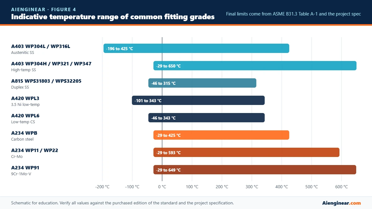
Use Figure 4 as a first filter, not as a design limit. Carbon steel above about 425 °C needs attention to graphitisation and creep; the Cr-Mo grades need correct post-weld heat treatment, and P91/WP91 needs tight control of normalising, tempering and hardness. For sour service, NACE MR0175 / ISO 15156 limits carbon steel hardness (typically 22 HRC maximum) and restricts some alloys, so the requirement must be written into the purchase order. For a deeper look at the forged carbon steel grade most used for B16.11 fittings, see our ASTM A105 guide.
Mechanical properties of common fitting grades
Aienginear · Table 8
Minimum mechanical properties of common fitting grades
Room-temperature values per the ASTM specification
| Grade | Product | Tensile strength, MPa | Yield strength min, MPa | Special requirement |
|---|---|---|---|---|
| A234 WPB | Wrought CS | 415 – 585 | 240 | — |
| A234 WPC | Wrought CS | 485 – 655 | 275 | — |
| A420 WPL6 | Wrought low-temp CS | 415 – 585 | 240 | Charpy impact at −46 °C |
| A234 WP11 Cl.1 / WP22 Cl.1 | Wrought Cr-Mo | 415 – 585 | 205 | Heat treatment per spec |
| A234 WP91 Type 1 | Wrought 9Cr-1Mo-V | 585 – 760 | 415 | Normalised and tempered, hardness limits |
| A403 WP304 | Wrought austenitic SS | 515 min | 205 | Solution annealed |
| A403 WP304L / WP316L | Wrought austenitic SS | 485 min | 170 | Solution annealed |
| A815 WPS31803 | Wrought duplex SS | 620 min | 450 | Ferrite balance, solution annealed |
| A105 | Forged CS | 485 min | 250 | Hardness 197 HBW max |
| A350 LF2 Cl.1 | Forged low-temp CS | 485 – 655 | 250 | Charpy impact at −46 °C |
| A182 F316L | Forged austenitic SS | 485 min | 170 | Solution annealed |
Elongation, hardness and supplementary requirements vary by grade and class; check the current ASTM edition. © Aienginear.com
Fitting marking and certificates
Each B16.9 or B16.11 fitting must be marked with the manufacturer’s name or trademark, the material grade, the schedule or wall (or class for forged fittings) and the size. Heat number and the standard designation are normally added by the manufacturer or required by the purchaser. A typical wrought elbow reads: MFR · A234 WPB-S · SCH 40 · 6" · B16.9 · HT 4A217. Where marking would damage a small fitting, a metal tag is acceptable.
Ask for an EN 10204 type 3.1 inspection certificate (or 3.2 where the owner’s inspector witnesses) showing heat number, chemistry, mechanical results, heat treatment and any supplementary tests. The heat number on the certificate must match the heat number stamped on the fitting. Detailed marking and NDT checks are covered in our pipe fittings inspection guide.
Dimensional inspection checklist
Receiving inspection should confirm that each fitting matches the purchase order, the standard and the pipe it will be welded to. Measure the items below on a sample set by the inspection and test plan, and on every fitting for critical or high-alloy service.
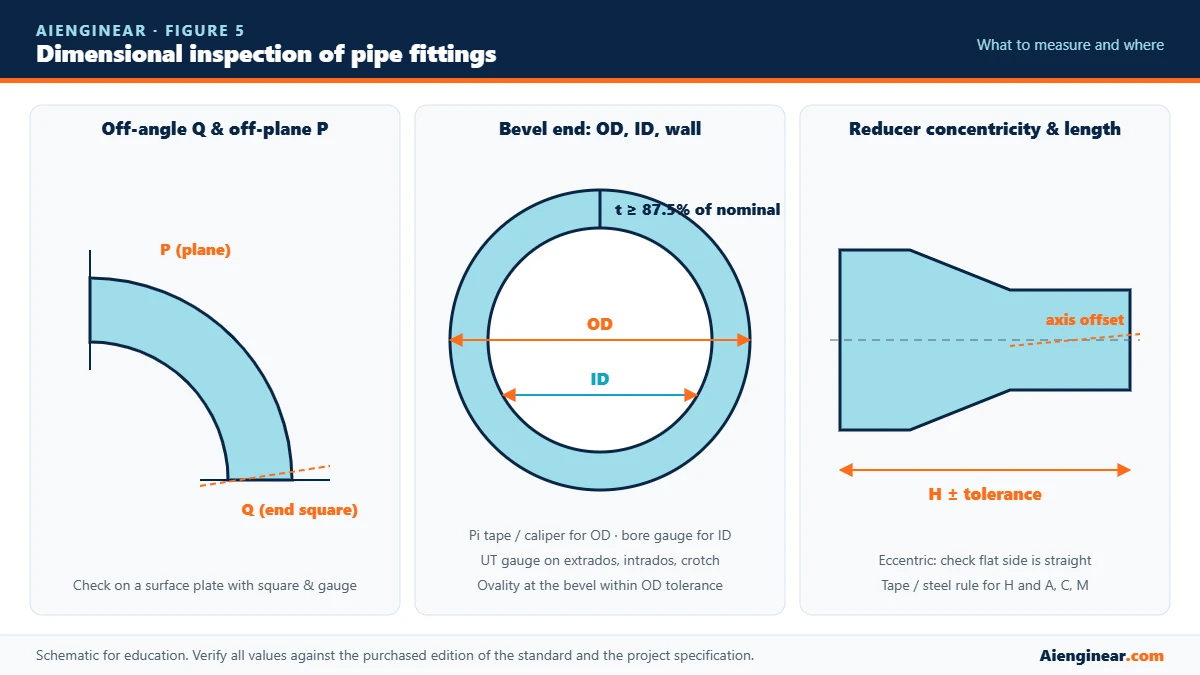
Aienginear · Table 9
Pipe fitting dimensional inspection checklist
Print this table and use it at receiving inspection
| # | Check | Tool | Acceptance basis | Result |
|---|---|---|---|---|
| 1 | Marking, heat number and certificate match the PO | Visual, MTC review | PO, B16.9 / B16.11 marking, MSS SP-25 | ☐ |
| 2 | OD at the welding end, including ovality | Pi tape, vernier caliper | B16.9 OD tolerance (Table 3) | ☐ |
| 3 | ID at the welding end | Bore gauge, inside caliper | B16.9 ID tolerance, match to pipe bore | ☐ |
| 4 | Wall thickness at extrados, intrados, crotch and ends | Ultrasonic thickness gauge | Not less than 87.5 % of nominal wall | ☐ |
| 5 | Centre-to-end A, B, C, M and overall length H, E | Steel tape, square, straight edge | Table 2 values ± Table 3 tolerances | ☐ |
| 6 | Off-angle Q (end squareness) and off-plane P | Surface plate, square, feeler gauge | B16.9 Q and P limits | ☐ |
| 7 | Elbow angle (45°, 90°, 180°) | Protractor, template | Within Q and centre-to-end tolerance | ☐ |
| 8 | Reducer concentricity or eccentric flat side | Straight edge, centring gauge | Axis alignment within H and OD tolerances | ☐ |
| 9 | Bevel angle, root face and land | Bevel protractor, weld gauge | B16.25: 37.5° ± 2.5°, root 1.6 ± 0.8 mm | ☐ |
| 10 | Socket bore, socket depth or thread gauging (forged) | Plug gauge, depth gauge, NPT ring/plug | B16.11, ASME B1.20.1 | ☐ |
| 11 | Surface: laps, cracks, gouges, rust, end protection | Visual, MT/PT if suspect | Spec workmanship clause; depth within min wall | ☐ |
| 12 | Positive material identification (alloys) | XRF / OES PMI analyser | Project PMI procedure, ASTM grade chemistry | ☐ |
Record actual readings, not just pass/fail, so out-of-tolerance trends can be raised with the supplier. © Aienginear.com
Common mistakes to avoid
- Citing ASME B16.28. It was withdrawn; SR elbows are now in B16.9.
- Ordering “STD” when the line is Sch 40 at NPS 12 and above. STD is 9.53 mm at NPS 12, Sch 40 is 10.31 mm, so the bores will not match.
- Leaving out the -S / -W / -WX suffix. You may receive welded fittings where seamless or fully radiographed ones were intended.
- Using A234 WPB in low-temperature service. It has no impact test requirement; use A420 WPL6 with impact testing.
- Treating forged class 3000 as “3000 psi”. The class only pairs the fitting with a pipe schedule.
- Bottoming socket-weld pipe. Always leave the ≈ 1.5 mm gap.
- Skipping PMI on alloy fittings. Mixed-up Cr-Mo and stainless fittings look identical once painted.
Key takeaways
- Butt-weld fittings use the pipe’s NPS/DN and schedule; OD is fixed by size, bore by schedule.
- ASME B16.9-2024 covers NPS ½ – 48 butt-weld fittings, including SR elbows formerly in B16.28.
- Minimum fitting wall is 87.5 % of nominal; thicker fittings are taper-trimmed (≤ 30°) to match the pipe bore.
- ASME B16.11-2021 forged fittings are ordered by class: 3000 SW matches Sch 80, 6000 SW matches Sch 160, 9000 SW matches XXS.
- Order fitting grades from the same family as the pipe (A106 B → A234 WPB / A105; A312 316L → A403 WP316L / A182 F316L).
- Inspect OD, ID, wall, centre-to-end, Q, P, bevel and marking, and run PMI on alloys.
Frequently asked questions
What standard covers pipe fitting dimensions?
ASME B16.9-2024 covers factory-made wrought butt-weld fittings from NPS ½ to 48, including long- and short-radius elbows, tees, reducers, caps and returns. ASME B16.11-2021 covers forged socket-weld and threaded fittings from NPS ⅛ to 4.
Is ASME B16.28 still valid?
No. ASME B16.28 for short-radius elbows and returns was withdrawn and its content was absorbed into ASME B16.9. New specifications should reference B16.9 for SR elbows.
What is the centre-to-end dimension of a 90° long-radius elbow?
For NPS 1 and larger it is 1.5 times the nominal size in inches, converted to millimetres. For example, a 6 in LR elbow is 229 mm and a 12 in LR elbow is 457 mm. NPS ½ and ¾ have special values of 38 mm and 29 mm.
What is the minimum wall thickness of a butt-weld fitting?
ASME B16.9 requires the wall at any point to be at least 87.5 % of the nominal wall thickness of the pipe schedule ordered.
What does class 3000 mean for a forged fitting?
It is a class designation, not a pressure. A class 3000 socket-weld fitting is designed to match Sch 80 pipe, and a class 3000 threaded fitting matches Sch 160 pipe.
Which fitting material matches A106 Grade B pipe?
ASTM A234 WPB for butt-weld fittings and ASTM A105 for forged socket-weld or threaded fittings. For low-temperature service, switch to A333 Gr 6 pipe with A420 WPL6 and A350 LF2 fittings.
What do WP-S, WP-W and WP-WX mean?
They describe how the fitting was made: S is seamless, W is welded, WX is welded with 100 % radiography of the welds and WU is welded with 100 % ultrasonic examination.
Why leave a gap in socket-weld joints?
A gap of about 1.5 mm between the pipe end and the socket bottom allows thermal expansion during welding and service, preventing cracking at the fillet weld root.
Aienginear · Quiz
Test your knowledge: pipe fittings dimensions and materials
10 questions · instant feedback with explanations
References
- ASME B16.9-2024, Factory-Made Wrought Buttwelding Fittings. ASME, New York.
- ASME B16.11-2021, Forged Fittings, Socket-Welding and Threaded. ASME, New York.
- ASME B16.25-2022, Buttwelding Ends. ASME, New York.
- ASME B36.10M and B36.19M, Welded and Seamless Wrought Steel Pipe; Stainless Steel Pipe. ASME, New York.
- ASME B31.3, Process Piping (Table 326.1, para. 304.7.2, Fig. 328.4.3, Fig. 328.5.2C).
- ASTM A234/A234M-24, A403/A403M-25, A420/A420M, A815/A815M, A105/A105M-26, A182/A182M, A350/A350M. ASTM International.
- MSS SP-25, SP-75, SP-95, SP-97. Manufacturers Standardization Society.
- NACE MR0175 / ISO 15156, Materials for use in H₂S-containing environments.
Related on Aienginear: Types of pipe fittings · Pipe fittings manufacturing process · Pipe fittings inspection · Pipe inspection, testing and marking · 50 piping interview questions

Written by Muhammad Raza
Founder of Aienginear. Engineering and digital solutions professional with 26+ years managing projects, plant shutdowns and turnarounds in oil & gas, petrochemical and power generation.