
HYDROTEST · PNEUMATIC TEST · ASME B31.3 / B31.1 · UPDATED OCTOBER 2026
Quick answer: how do you calculate hydrotest pressure?
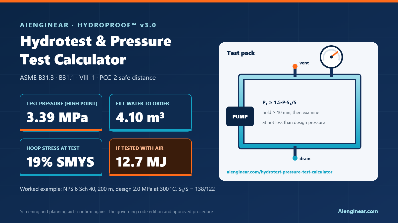
For ASME B31.3 process piping, the hydrostatic test pressure is PT = 1.5 × P × (ST/S), where P is the design gauge pressure and ST/S is the allowable stress at test temperature divided by the allowable stress at design temperature (taken between 1.0 and 6.5). ASME B31.1 power piping uses 1.5 × design pressure, and a B31.3 pneumatic test uses 1.1 × design pressure. The pressure must be reached at the highest point, held for at least 10 minutes, and must not overstress the lowest point or any component in the loop.
Example: a carbon steel line designed for 2.0 MPa at 300 °C with ST = 138 MPa and S = 122 MPa needs 1.5 × 2.0 × 1.131 = 3.39 MPa(g). The calculator below also gives the fill water, temperature drift, gauge and relief settings, pneumatic stored energy and a printable test-pack report.
How to use the calculator
- Tab 1, Test pressure: pick the code and test type, enter the design pressure and the allowable stresses at test and design temperature. Add the governing pipe size, wall and yield strength, the height from the high point to the low point and the lowest test rating of any component that stays in the loop.
- Tab 2, Volume and water: list every line in the test pack by NPS, schedule and length. The pipe database follows ASME B36.10M and B36.19M. Add any vessel or equipment volume, the reserve for venting and losses, and the tanker size.
- Tab 3, Temperature and gauges: enter the water temperature change you expect during the hold. The tool shows how much pressure that adds, picks a gauge range and gives the maximum test relief valve set pressure.
- Tab 4, Pneumatic safety: only if water cannot be used. It shows the stored energy, TNT equivalent, a screening distance and a stepped pressurising plan.
- Tab 5, Pump, time and cost: fill and test pump sizes, total duration, man-hours and cost.
- Tab 6, Report: add the pack number and names, then print or save a PDF with signature boxes, export CSV, or log the pack in the register.
Every value updates as you type. SI and US units are supported, and the pressure unit can be MPa, bar, kPa or psi. Inputs stay on your device; nothing is uploaded.
What is new in version 3.0
Aienginear Table 1
HydroProof v3.0 changes and corrections
Compared with v2.0 (June 2026)
| Area | v2.0 | v3.0 |
|---|---|---|
| B31.1 pneumatic factor | 1.1 × design pressure | 1.2 × design, with the 1.5 × upper bound |
| Stress ratio | Could fall below 1.0, giving less than 1.5 × P | Taken between 1.0 and 6.5, so the 1.5 × P floor always holds |
| Upper limit | Not checked | Hoop stress at minimum wall against yield (100% hydro, 90% pneumatic), B31.3 pneumatic 1.33 × P cap and component rating |
| Static head | Not included | Pressure at the low point and at the gauge from the elevation difference |
| Vessel in the loop | Not included | B31.3 345.4.3 77% check |
| ASME VIII-1 vessels | Not included | UG-99 hydro (1.3 × MAWP × LSR) and UG-100 pneumatic |
| Test-pack volume | One pipe size only | Unlimited lines from a B36.10M / B36.19M database, plus equipment |
| Thermal pressure rise | Simplified | Restrained-pipe relation with temperature-dependent water properties |
| Test pump | Fill pump only | Also the water needed to pressurise (compression plus pipe stretch) |
| TNT equivalence | 4.6 MJ/kg fixed | 4.184 MJ/kg default, editable; distance has a procedure minimum |
| Pneumatic plan | None | Preliminary check, stepped pressurising and examination pressure |
| Report | Text-only PDF | Branded print/PDF report with line list, steps and signature boxes |
| Scope | Included weld-repair deposition | Removed (see the welding cost calculator); placeholder ad boxes removed |
Source: Aienginear HydroProof release notes, October 2026.
Test pressure by code
Each construction code sets a minimum test pressure, a hold time, and a ceiling that protects the piping from the test itself. The table summarises the rules the calculator applies. Always check the edition named in your contract, because clause numbers and limits are revised from time to time.
Aienginear Table 2
Hydrostatic and pneumatic test pressure by code
P = design gauge pressure (MAWP for vessels) · minimum hold 10 minutes unless noted
| Code | Hydrostatic test | Pneumatic test | Upper limit | Examination |
|---|---|---|---|---|
| ASME B31.3 (345.4, 345.5) | 1.5 × P × ST/S, ratio ≤ 6.5 | 1.1 × P, raised in steps after a low-pressure leak check | Hydro: stress not above yield at test temperature. Pneumatic: lesser of 1.33 × P and the pressure giving 90% of yield | After 10 min; may reduce to not less than design pressure. Pneumatic: reduce to design pressure |
| ASME B31.1 (137.4, 137.5) | 1.5 × P at every point in the system | 1.2 × P to 1.5 × P | Maximum test pressure of any non-isolated component | After at least 10 min at test pressure |
| ASME VIII-1 (UG-99, UG-100) | 1.3 × MAWP × LSR | 1.1 × MAWP × LSR | Vessel general membrane stress limits in UG-99 / UG-100 | Hydro: at not less than PT/1.3. Pneumatic: at PT/1.1 |
| B31.3 Category D | Initial service leak test (345.7) may replace the hydrotest at the owner’s option | – | Operating pressure | During service start-up |
| B31.3 Category M | Hydro or pneumatic as above | Plus a sensitive leak test (345.8) | As above | As above |
LSR = lowest ratio of allowable stress at test temperature to allowable stress at design temperature. Summary for planning; the code text governs.
The stress ratio ST/S
A hot system is designed with the lower allowable stress of the metal at its design temperature. When the same piping is tested cold, the metal is stronger, so B31.3 raises the test pressure in proportion. That is why a line designed for 2.0 MPa at 300 °C is tested at 3.39 MPa rather than 3.0 MPa.
ST = allowable stress at test temperature | S = allowable stress at design temperature
- Use the component with the lowest ratio in the pack, because that component must not be over-tested. Pipe, fittings, flanges and valves of different materials can have different ratios.
- When design temperature is at or below test temperature, the ratio is 1.0 and the test is simply 1.5 × P.
- The 6.5 cap only matters at very high design temperatures where the allowable stress is low, for example creep-range alloy steels.
- Take S and ST from ASME B31.3 Table A-1 (or A-1M) for the edition you are working to; the example values in this article are for illustration.
Upper limits: yield, components and static head
A pressure test proves strength and tightness, but it must not damage what it proves. Three checks set the ceiling, and the calculator runs all of them.
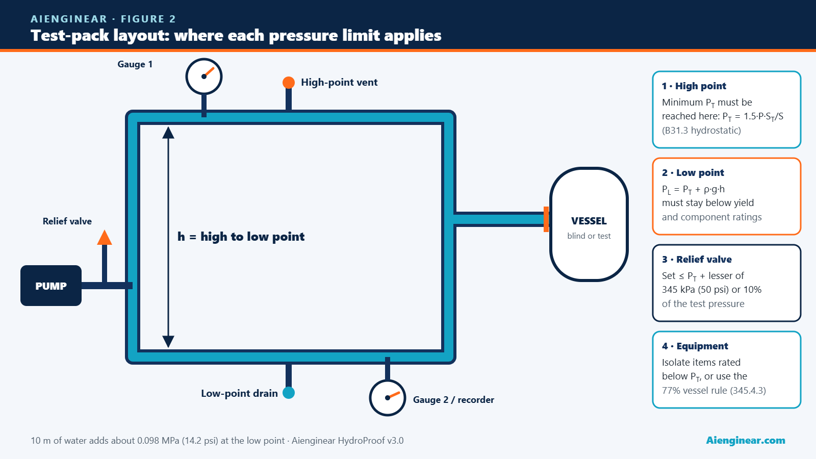
Yield. B31.3 lets you reduce the hydrostatic test pressure if it would stress any component above yield at the test temperature; for pneumatic tests the ceiling is 90% of yield and 1.33 × P. The tool checks hoop stress, PL × OD / (2 × tmin), at the minimum wall after mill tolerance.
Components. Flanges, valves, expansion joints, instruments and equipment often have a lower test rating than the pipe. Remove them, blind them off or test them separately. Where a vessel cannot be isolated, B31.3 345.4.3 allows the piping to be tested at the vessel test pressure if that is at least 77% of the piping test pressure.
Static head. Water adds about 0.098 MPa (14.2 psi) for every 10 m of height. The code minimum must be reached at the highest point, so the lowest point sees more. On tall structures, risers and pipe racks this can push the low point over the limit, and the pack has to be split by elevation.
Aienginear Table 3
Static head of test water by elevation difference
Water at 20 °C, ρ = 998.2 kg/m³, g = 9.80665 m/s²
| High point to low point | Extra pressure (MPa) | Extra pressure (bar) | Extra pressure (psi) |
|---|---|---|---|
| 5 m (16 ft) | 0.049 | 0.49 | 7.1 |
| 10 m (33 ft) | 0.098 | 0.98 | 14.2 |
| 20 m (66 ft) | 0.196 | 1.96 | 28.4 |
| 30 m (98 ft) | 0.294 | 2.94 | 42.6 |
| 50 m (164 ft) | 0.489 | 4.89 | 71.0 |
Add this to the high-point test pressure to get the low-point pressure. Source: Aienginear calculation.
Worked example: 6-inch carbon steel process line
Inputs used in the calculator’s default case: ASME B31.3, hydrostatic; design 2.0 MPa at 300 °C; ST = 138 MPa, S = 122 MPa (illustrative); 200 m of NPS 6 Sch 40 (OD 168.3 mm, wall 7.11 mm, 12.5% mill tolerance); yield 241 MPa; flat pack with no elevation difference; water at 20 °C.
Aienginear Table 4
Worked example: NPS 6 Sch 40, 200 m, B31.3 hydrotest
Each step matches a row in the calculator output
| Step | Working | Result |
|---|---|---|
| 1. Stress ratio | 138 / 122, between 1.0 and 6.5 | 1.131 |
| 2. Test pressure | 1.5 × 2.0 × 1.131 | 3.39 MPa(g) at the high point |
| 3. Minimum wall | 7.11 × (1 − 0.125) | 6.22 mm |
| 4. Hoop stress | 3.39 × 168.3 / (2 × 6.22) | 45.9 MPa = 19% of yield |
| 5. Yield-limited pressure | 241 × 2 × 6.22 / 168.3 | 17.8 MPa, ample margin |
| 6. Pack volume | (π/4) × 0.15408² × 200 | 3.73 m³ |
| 7. Fill water | 3.73 × 1.10 reserve | 4.10 m³ (4.09 t) |
| 8. Gauge | Range about 2 × reading | 0 to 6 MPa, reading at 57% of span |
| 9. Relief valve | 3.39 + lesser of 0.345 or 0.339 | Set not above 3.73 MPa |
| 10. Temperature drift | 0.33 MPa per °C × 3 °C | About +0.98 MPa if the water warms 3 °C |
| 11. Hold and examine | B31.3 345.2.2 | 10 min minimum, examine at not less than 2.0 MPa |
Allowable stresses are illustrative. Use ASME B31.3 Table A-1 values for your material and edition. Source: Aienginear HydroProof v3.0.
Why add only 10% reserve? The reserve covers venting, flushing of the high points, small top-ups and losses at blinds. For long pipelines, dirty lines that need a flush, or remote sites with slow tanker turnaround, use 20% to 30%.
Temperature drift during the hold
Water barely compresses, so once a line is full and sealed a small temperature change moves the pressure a lot. Warming pushes the test above the planned value; cooling can look like a leak. The calculator uses the restrained-pipe relation, which accounts for both the water and the stretch of the pipe wall:
β = water expansion · α = steel expansion · κ = water compressibility · D, t = pipe ID and wall · E, ν = steel modulus and Poisson’s ratio
Aienginear Table 5
Pressure change per °C of water temperature
Liquid-full, air-free system · steel E = 200 GPa, α = 12 × 10⁻⁶ /°C, ν = 0.3
| Water temperature | Rigid container (MPa/°C) | NPS 6 Sch 40 (MPa/°C) | NPS 12 Sch 40 (MPa/°C) |
|---|---|---|---|
| 10 °C | 0.18 | 0.11 | 0.10 |
| 15 °C | 0.32 | 0.22 | 0.21 |
| 20 °C | 0.45 | 0.33 | 0.31 |
| 25 °C | 0.57 | 0.42 | 0.40 |
| 30 °C | 0.68 | 0.51 | 0.48 |
Trapped air greatly reduces these values and makes the test unstable, so vent thoroughly. Source: Aienginear calculation from IAPWS water properties.
In practice: fill with water close to ambient temperature, let it settle before starting the hold, shade exposed lines, and record water and metal temperature next to every pressure reading. If the pressure drifts, compare the change with the temperature record before suspecting a leak.
Gauges and relief valves
- Range: ASME VIII-1 UG-102 asks for a gauge range of about twice the test pressure, never less than 1.5 times or more than 4 times. Many piping procedures adopt the same rule. The calculator suggests the nearest standard range.
- Number and position: use at least one calibrated gauge connected directly to the system, plus a second gauge or a chart recorder as your procedure requires. If the gauge is not at the high point, correct its reading for static head (Tab 1 does this).
- Calibration: in date, with the certificate in the test pack. Accuracy class 1.0 on a 0 to 6 MPa gauge is ±0.06 MPa.
- Relief valve: B31.3 345.5.1 requires one for pneumatic tests, set no higher than the test pressure plus the lesser of 345 kPa (50 psi) or 10% of the test pressure. Most owners also fit one on hydrotests to protect against thermal rise and pump overshoot.
Fill water and test water quality
The internal volume drives tanker loads, fill time, pump size, disposal cost and the extra load on pipe supports. The table gives quick figures for Schedule 40 pipe.
Aienginear Table 6
Hydrotest water volume and weight, Schedule 40 pipe
ASME B36.10M dimensions · water at 20 °C
| NPS | OD (mm) | ID (mm) | m³ per 100 m | Water load (kg/m) | US gal per 100 ft |
|---|---|---|---|---|---|
| 2 | 60.3 | 52.5 | 0.216 | 2.2 | 17.4 |
| 3 | 88.9 | 77.9 | 0.477 | 4.8 | 38.4 |
| 4 | 114.3 | 102.3 | 0.821 | 8.2 | 66.1 |
| 6 | 168.3 | 154.1 | 1.865 | 18.6 | 150 |
| 8 | 219.1 | 202.7 | 3.228 | 32.2 | 260 |
| 10 | 273.1 | 254.6 | 5.089 | 50.8 | 410 |
| 12 | 323.9 | 303.3 | 7.224 | 72.1 | 582 |
| 14 | 355.6 | 333.3 | 8.727 | 87.1 | 703 |
| 16 | 406.4 | 381.0 | 11.40 | 113.8 | 918 |
| 18 | 457.2 | 428.7 | 14.43 | 144.1 | 1,162 |
| 20 | 508.0 | 477.8 | 17.93 | 179.0 | 1,444 |
| 24 | 609.6 | 574.6 | 25.93 | 258.9 | 2,088 |
Check that supports and spring hangers designed for gas or vapour service can carry the water load; lock springs or add temporary supports. Source: Aienginear calculation.
Water quality matters as much as quantity. Use clean, filtered water and follow the project limits. The calculator screens chloride and pH with common project values, not code values:
Aienginear Table 7
Test water screening limits used in the calculator
Typical project values · the owner specification governs
| Material | Chloride (ppm, max) | pH | After the test |
|---|---|---|---|
| Carbon steel | 250 | 6.0 to 9.0 | Drain promptly; inhibitor if water stays more than a few days |
| Austenitic stainless 304/316 | 50 | 6.0 to 8.5 | Drain and dry quickly to avoid chloride pitting and stress corrosion cracking |
| Duplex stainless | 200 | 6.0 to 9.0 | Drain and dry |
| Lined or coated pipe | 250 | 6.0 to 9.0 | Check lining compatibility and temperature limits |
Source: Aienginear summary of common project practice. Not a code requirement.
Pneumatic tests and stored energy
Gas is compressible, so a pressurised gas stores energy that is released in a blast if the system fails. Water stores almost none. That single fact is why every code prefers the hydrostatic test, and why B31.3 345.5 lets you use a pneumatic test only where water would damage the system, cannot be removed, or would freeze, and only with owner approval and a written procedure.
WTNT = E / 4.184 MJ/kg R = Rs · W1/3, Rs ≈ 20 m/kg1/3 (screening)
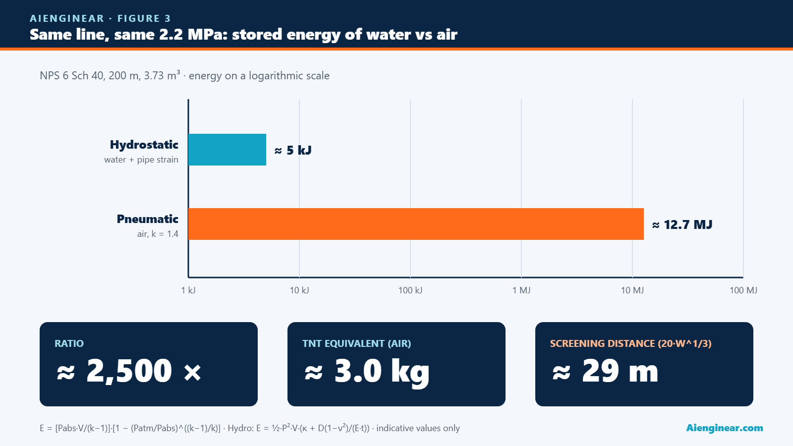
This is the isentropic expansion energy used in ASME PCC-2 Article 501. For the worked example tested with air at 1.1 × 2.0 = 2.2 MPa(g), the 3.73 m³ line stores about 12.7 MJ, roughly 3.0 kg of TNT, giving a screening distance near 29 m. The same line filled with water at the same pressure stores about 5 kJ: some 2,500 times less.
Aienginear Table 8
Stored energy per cubic metre of air at test pressure
k = 1.4 · TNT 4.184 MJ/kg · screening distance 20 · W1/3 · water value excludes pipe strain
| Test pressure (gauge) | Air energy (MJ/m³) | TNT (kg/m³) | Screening distance for 1 m³ | Water energy (kJ/m³) | Air / water |
|---|---|---|---|---|---|
| 0.5 MPa (72.5 psi) | 0.60 | 0.14 | 10.5 m | 0.06 | ~10,000 × |
| 1.0 MPa (145 psi) | 1.36 | 0.33 | 13.8 m | 0.23 | ~5,900 × |
| 2.0 MPa (290 psi) | 3.04 | 0.73 | 18.0 m | 0.92 | ~3,300 × |
| 3.5 MPa (508 psi) | 5.76 | 1.38 | 22.2 m | 2.81 | ~2,000 × |
| 5.0 MPa (725 psi) | 8.59 | 2.05 | 25.4 m | 5.74 | ~1,500 × |
Energy scales with volume; distance scales with the cube root of energy. Screening values only: fragment throw, barricades and site layout must be assessed per ASME PCC-2 Article 501 and your procedure. Source: Aienginear calculation.
The distance in the calculator is not an exclusion zone. It is a blast-overpressure screening value to show the size of the hazard. The approved exclusion zone comes from a site-specific risk assessment that also considers fragments, brittle-fracture risk of the material at test temperature, barricades, occupied buildings and access control.
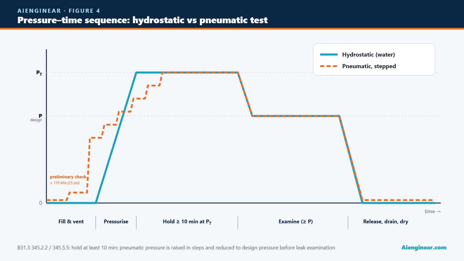
For pneumatic tests, B31.3 345.5.5 requires a preliminary check at a low pressure (not more than 170 kPa, 25 psi), then a gradual rise in steps, holding each step long enough for strains to equalise. After the hold at test pressure, the pressure is reduced to design pressure before anyone approaches to examine the joints. Tab 4 builds this step plan for you.
Test sequence and test-pack checklist
Test-pack checklist
- Test limits, blinds and spades marked on the isometrics and P&IDs; blind thickness checked for the test pressure.
- All welding, heat treatment and NDE complete and accepted; joints left uninsulated and unpainted for examination unless the code allows otherwise.
- Instruments, control valves, relief valves, expansion joints and items rated below the test pressure removed or isolated.
- Supports able to carry the water load; spring hangers locked.
- Vents at every high point and drains at every low point; air fully removed before pressurising.
- Calibrated gauges (range about 2 × test pressure), recorder if required, and test relief valve set and tagged.
- Brittle fracture considered: test temperature above the material’s minimum design metal temperature with margin.
- Barricades and signs in place; only authorised people inside the zone.
- Hold of at least 10 minutes, then examination at not less than design pressure; results signed by the inspector.
- Controlled depressurising with vents open to avoid vacuum, then drain, dry and preserve as specified.
Common hydrotest mistakes
Aienginear Table 9
Hydrotest mistakes, consequences and prevention
From site and turnaround experience
| Mistake | What happens | Prevention |
|---|---|---|
| Test pressure read at the low point | High point is under-tested; the test is invalid | Set the minimum at the high point; correct gauge readings for head |
| Ignoring static head on tall packs | Low point overstressed or a flange over-tested | Check PL against yield and ratings; split by elevation |
| Air left in the system | Slow, unstable pressurising; stored energy rises | Fill from the low point, vent every high point, check water added against Tab 5 |
| Sun on a sealed line | Pressure climbs above the test value | Shade, test early in the day, fit a relief valve |
| Control valve or instrument left in | Damaged trim, diaphragms or sensors | Remove or isolate; use spool pieces |
| High-chloride water in stainless | Pitting or chloride stress corrosion cracking | Low-chloride water; drain and dry promptly |
| Supports not checked for water weight | Sagging, spring damage, overloaded nozzles | Temporary supports, locked springs |
| Fast depressurising with vents shut | Vacuum collapse of thin-wall pipe or tanks | Open vents while draining |
Source: Aienginear field notes from plant shutdowns and turnarounds.
How this calculator compares
Aienginear Table 10
Aienginear HydroProof v3.0 vs typical online hydrotest calculators
Feature check, October 2026
| Feature | Typical calculator | Aienginear HydroProof v3.0 |
|---|---|---|
| Codes | B31.3 only, or a fixed 1.5 factor | B31.3, B31.1, ASME VIII-1 and custom; hydro and pneumatic |
| Stress ratio | Often missing or uncapped | Bounded 1.0 to 6.5 (B31.3), LSR for vessels |
| Maximum test pressure | Rarely checked | Yield at minimum wall, code cap and component rating |
| Static head and gauge position | No | Yes, high point, low point and gauge reading |
| Test-pack volume | Single pipe | Multi-line list with B36.10M / B36.19M database plus equipment |
| Thermal drift | No | Restrained-pipe dP/dT with water properties |
| Gauge and relief settings | No | UG-102 range check and 345.5.1 relief set |
| Pneumatic safety | Energy only, if at all | Energy, TNT, screening distance, step plan, hydro comparison |
| Planning | No | Fill and test pump, duration, man-hours, cost |
| Output | Screen only | Branded print/PDF report, CSV, share link, pack register |
| Privacy and cost | Sign-up or ads inside the tool | Free, no sign-up, runs in your browser |
Source: Aienginear review of commonly used free online tools.
Standards and references
Aienginear Table 11
Standards behind the calculator
Use the edition named in your contract
| Document | Used for |
|---|---|
| ASME B31.3 Process Piping, Chapter VI (345) | Hydrostatic, pneumatic, sensitive and initial service leak tests; stress ratio; vessel in loop; relief setting |
| ASME B31.1 Power Piping, Chapter VI (137) | Hydrostatic and pneumatic test pressures and limits |
| ASME BPVC Section VIII Division 1 (UG-99, UG-100, UG-102) | Vessel hydrostatic and pneumatic tests, gauge range |
| ASME PCC-2 Article 501 | Pressure and tightness testing practice, stored energy and safe distance |
| ASME B36.10M and B36.19M | Pipe outside diameters and wall thicknesses |
| IAPWS water properties | Density, compressibility and expansion of test water |
| API 570 / API 510 | Pressure testing of in-service piping and vessels after repair or alteration |
Source: Aienginear. Code text governs over any summary on this page.
Quick quiz: test your hydrotest knowledge
Related Aienginear calculators and guides
Frequently asked questions
How do you calculate hydrotest pressure as per ASME B31.3?
Multiply the design gauge pressure by 1.5 and by the ratio of the allowable stress at test temperature to the allowable stress at design temperature. The ratio is not less than 1.0 and not more than 6.5. The result is the minimum pressure at the highest point of the system, and it may be reduced if it would stress any component above yield at the test temperature.
What is the hydrotest pressure for ASME B31.1 power piping?
B31.1 requires at least 1.5 times the design pressure at every point in the system, without a stress-ratio factor, and not more than the maximum test pressure of any non-isolated component. A B31.1 pneumatic test is between 1.2 and 1.5 times design pressure.
What is the pneumatic test pressure under B31.3?
At least 1.1 times design pressure, not exceeding the lesser of 1.33 times design pressure or the pressure that would cause 90% of yield stress. A preliminary leak check is made at a low pressure, the pressure is raised in steps, and it is reduced to design pressure before the joints are examined.
How long must a hydrotest be held?
B31.3 and B31.1 require the test pressure to be held for at least 10 minutes before the examination for leaks. Many owner specifications ask for longer holds, such as 30 minutes or more for buried or large systems, and some require a chart record.
Does static head count towards the hydrotest pressure?
The minimum test pressure must exist at the highest point, so the low point is higher by the static head, about 0.098 MPa (14.2 psi) per 10 m of water. The calculator adds this and checks the low point against yield and component ratings.
How much water is needed for a hydrotest?
The internal volume of all lines and equipment in the test pack plus a reserve, typically 10% to 30%, for venting, flushing and losses. A 100 m run of NPS 6 Schedule 40 pipe holds about 1.87 m³ (about 493 US gallons).
Why is a pneumatic test more dangerous than a hydrotest?
Gas stores energy when compressed and releases it as a blast if the system fails, while water hardly compresses. At the same pressure and volume, air stores roughly a thousand to ten thousand times more energy than water, so pneumatic tests need owner approval, a written procedure and a formal exclusion zone.
What range of pressure gauge should be used for a hydrotest?
A range of about twice the test pressure, and never less than 1.5 times or more than 4 times, as ASME VIII-1 UG-102 states and many piping procedures follow. Gauges must be calibrated, and a second gauge or a chart recorder is usually required.
Can this calculator be used for a live test pack?
It is a screening and planning aid. Test pressures, limits and every safety distance must be confirmed against the governing code edition, the engineering dossier and an approved test procedure, and the test must be witnessed as your quality plan requires.
Disclaimer. This page and the HydroProof calculator support engineering judgement; they do not replace it. Code clauses are summarised in our own words for planning; the purchased code text and your approved procedure govern. Report an error through the contact page and we will review it.

Written by Muhammad Raza
Founder of Aienginear. Engineering and digital solutions professional with 26+ years managing projects, plant shutdowns and turnarounds in oil & gas, petrochemical and power generation.