
AIENGINEAR · FLOWSTACK™ · HUB 01 OF 03
FlowStack is the Aienginear hub for process and hydraulics calculations. It gathers 13 free calculators that take a liquid, gas or steam service from its physical properties to a sized line, a known pressure drop, a selected pump or compressor, a sized control valve or flow meter, and a separator or exchanger. This page explains the workflow, gives the screening criteria engineers actually use, and includes a quick line and NPSH checker you can run right here.
What are process and hydraulics calculators?
Process and hydraulics calculators apply fluid-mechanics equations — mainly the Darcy-Weisbach equation, an energy balance and standard flow-meter and valve-sizing methods — to find line sizes, pressure losses, pump head, NPSH margin, valve Cv and flow rates. FlowStack bundles 13 such tools from Aienginear. They follow recognised references including ISO 5167 for orifice and Venturi meters, IEC 60534-2-1 for control valves, API RP 14E for erosional velocity and API 12J for separators, and they run free in any browser.
1. The FlowStack workflow: properties to equipment
Hydraulic calculations fail most often at the start, not the end. A wrong viscosity or vapour pressure carries through every later step. FlowStack follows the order an experienced process engineer works in, so each result becomes the next tool’s input.
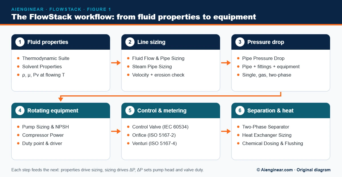
- Fix the fluid properties at flowing conditions: density, viscosity, vapour pressure and, for gases, compressibility.
- Select a line size from a velocity or pressure-drop criterion, then confirm erosional velocity for gas and two-phase lines.
- Calculate the full pressure drop: straight pipe, fittings, valves, equipment and elevation change.
- Size the rotating equipment from the system curve, and check NPSH or compressor discharge temperature.
- Size control valves and flow elements with the pressure drop you allotted to them.
- Size separators and exchangers, then confirm the hydraulic budget still closes.
2. All 13 FlowStack calculators
Every tool runs in the browser, shows the method it uses and prints a branded record. Click any name to open it.
Aienginear FlowStack · Table 1
FlowStack process and hydraulics calculators
13 free tools · grouped by workflow step
| Step | Calculator | Typical inputs | Key outputs | Method / standard |
|---|---|---|---|---|
| Fluid properties | Advanced Process & Thermodynamic Suite | Component, temperature, pressure | Vapour pressure, saturated-liquid density, hydraulic screening | Antoine, Rackett correlations |
| Fluid properties | Solvent Property & Sizing Calculator | Solvent, temperature, volume | Density at temperature, physical properties, hazard rating | Temperature-corrected density, NFPA 704 |
| Line sizing | Fluid Flow & Pipe Sizing Calculator (HydraFlow Pro) | Flow, fluid, allowable velocity or ΔP | Line size, velocity, gas-pipeline flow, erosional velocity | ASME B36.10M/19M data, API RP 14E, Weymouth/Panhandle/AGA |
| Line sizing | Steam Pipe Sizing Calculator | Steam flow, pressure, temperature | Minimum size on velocity and ΔP limits | Steam property data, actual pipe ID |
| Pressure drop | Pipe Pressure Drop Calculator | Flow, pipe, fittings, fluid | Friction and fitting loss for liquid, gas, steam, slurry, two-phase | Darcy-Weisbach, Colebrook-White, Crane TP-410 K-values |
| Rotating equipment | Pump Sizing Calculator | Flow, static head, losses, suction conditions | TDH, hydraulic and shaft power, NPSHa and margin | Energy balance, ANSI/HI NPSH concepts |
| Rotating equipment | Compressor Power & Performance Calculator | Gas, Ps, Pd, flow, stages | Head, power, discharge temperature, driver size | Real-gas Z, isentropic and polytropic methods |
| Control & metering | Control Valve Sizing Calculator | Flow, P1, P2, fluid, valve style | Cv/Kv, choked flow, cavitation, flashing, noise, opening | IEC 60534-2-1 (ISA-75.01.01 equivalent) |
| Control & metering | Orifice Plate Flow Calculator | ΔP, pipe ID, bore, fluid | Mass and volume flow or required bore; C and ε | ISO 5167-1 and -2, Reader-Harris/Gallagher |
| Control & metering | Venturi Meter Calculator | ΔP, throat and inlet diameter, fluid | Flow, discharge coefficient, beta ratio, permanent loss | ISO 5167-1 and -4 |
| Separation & heat | Two-Phase Separator Sizing Calculator | Gas and liquid rates, P, T, properties | Diameter, length, K-factor, liquid levels, retention | Souders-Brown, API 12J guidance |
| Separation & heat | Heat Exchanger Sizing Calculator | Stream data, temperatures, fouling | Duty, LMTD, F, area, shell-and-tube layout, ΔP | Bell-Delaware, TEMA screening |
| Separation & heat | Chemical Dosing & Flushing Calculator | System volume, target dose, flush velocity | Chemical quantity, dose rate, flushing volume | Mass balance, commissioning practice |
Reviewed 17 October 2026. Screening tools — verify against your design basis, vendor data and the code edition in your contract.
3. Quick line and NPSH checker
Use this to sanity-check a liquid line or a pump suction in seconds. The line check uses the Darcy-Weisbach equation with the Churchill friction factor, which covers laminar, transitional and turbulent flow in one expression. For gas, steam, two-phase or fittings, open the full calculators above.
Aienginear FlowStack · Free tool
Quick line and NPSH checker
Single-phase liquid · SI units · results update on Calculate
Enable JavaScript to use the checker, or follow the worked example below by hand.
Screening aid only. Defaults reproduce the worked examples on this page (water at 20 °C and 40 °C).
4. Line-sizing criteria: velocity and pressure-drop guides
Lines are sized against two limits at once: a velocity band that avoids erosion, noise and settling, and a pressure-drop budget that the pump or upstream pressure can afford. Table 2 gathers typical screening values used across the process industries. They are starting points, not rules — your client’s line-sizing specification always governs.
Aienginear FlowStack · Table 2
Typical line-sizing criteria by service
Screening velocity and pressure-drop guides
| Service | Typical velocity | Typical ΔP guide | Notes |
|---|---|---|---|
| Pump suction (liquid) | 0.6 – 1.5 m/s | ≈ 0.05 – 0.1 bar/100 m | Keep losses low to protect NPSHa |
| Pump discharge (liquid) | 1.5 – 3.0 m/s | ≈ 0.2 – 0.5 bar/100 m | Balance pipe cost against pumping energy |
| Gravity drain / overflow | 0.3 – 1.0 m/s | Set by available head | Size for self-venting flow |
| Cooling water | 1.0 – 3.0 m/s | ≈ 0.2 – 0.4 bar/100 m | Low velocity encourages fouling |
| Saturated steam (low pressure) | 15 – 25 m/s | Up to ≈ 0.1 bar/100 m | Use the Steam Pipe Sizing Calculator |
| Superheated steam | 30 – 60 m/s | Set by ΔP budget | Higher velocities allowed in dry steam |
| Process gas / compressed air | 10 – 20 m/s | Set by ΔP budget | Check noise near control valves |
| Two-phase and erosive service | Below erosional velocity | — | API RP 14E: Ve = C/√ρm (US units, C ≈ 100 continuous) |
Reviewed 17 October 2026. Typical screening values — your project design basis and company standards govern.
5. Pressure-drop methods by flow regime
For single-phase incompressible flow, the Darcy-Weisbach equation is the reference method: ΔP = f · (L/D) · ρv²/2. The Darcy friction factor f comes from the Colebrook-White equation (iterative) or an explicit fit such as Churchill or Swamee-Jain. Other regimes need other models:
Aienginear FlowStack · Table 3
Pressure-drop methods by flow regime
Which correlation to use, and when
| Regime | Primary method | Alternatives | Watch-outs |
|---|---|---|---|
| Single-phase liquid | Darcy-Weisbach + Colebrook-White | Churchill, Swamee-Jain (explicit) | Laminar: f = 64/Re |
| Gas, small ΔP (under ≈ 10 % of P1) | Darcy-Weisbach with average density | — | Use mean density between inlet and outlet |
| Gas, long lines / large ΔP | Isothermal compressible flow | Weymouth, Panhandle A/B, AGA | Check for choked (sonic) flow at the outlet |
| Two-phase gas-liquid | Beggs and Brill | Lockhart-Martinelli, homogeneous model | Flow pattern matters; elevation dominates in risers |
| Fittings and valves | K-method (Crane TP-410) | 2-K (Hooper), 3-K (Darby) | 3-K handles size and Reynolds effects best |
| Slurry | Durand-type deposition velocity | Settling-slurry models | Keep above deposition velocity |
Reviewed 17 October 2026. Method selection guide — confirm applicability ranges in the source correlation.
Worked example: water in a 4-inch Schedule 40 line
Water, 20 °C: ρ = 998.2 kg/m³, μ = 1.002 mPa·s
Q = 50 m³/h = 0.01389 m³/s;  NPS 4 Sch 40, ID = 102.3 mm;  L = 100 m;  ε = 0.045 mm

A  = π/4 × 0.1023² = 0.008219 m²
v  = 0.01389 / 0.008219 = 1.69 m/s
Re = 998.2 × 1.69 × 0.1023 / 0.001002 = 1.72 × 10⁵ (turbulent)
f  = 0.0188 (Colebrook-White, ε/D = 0.00044)
ΔP = 0.0188 × (100/0.1023) × 998.2 × 1.69² / 2 = 26,200 Pa
   = 0.262 bar per 100 m  (2.67 m of head)
The velocity sits inside the 1.5–3 m/s discharge band and the gradient is within a typical 0.2–0.5 bar/100 m budget, so NPS 4 is a reasonable discharge line for this duty. The quick checker above gives the same answer to within about 1 % (it uses the explicit Churchill friction factor).
6. Absolute pipe roughness values
Aienginear FlowStack · Table 4
Typical absolute roughness of pipe materials
Use in Colebrook-White or Churchill
| Material / condition | ε, mm | ε, in | Notes |
|---|---|---|---|
| Commercial carbon steel (new) | 0.045 | 0.0018 | Default for most process lines |
| Stainless steel, drawn | 0.015 | 0.0006 | Smooth; often used for clean services |
| Galvanised steel | 0.15 | 0.006 | Water and utility lines |
| Cast iron | 0.26 | 0.010 | Older water mains |
| Copper and brass tube | 0.0015 | 0.00006 | Hydraulically smooth |
| PVC, PE and HDPE | 0.0015 – 0.007 | 0.00006 – 0.0003 | Plastic piping |
| Concrete | 0.3 – 3.0 | 0.012 – 0.12 | Depends on finish |
| Corroded or scaled carbon steel | 0.15 – 1.0+ | 0.006 – 0.04+ | Use for ageing or fouled systems |
Reviewed 17 October 2026. Typical published values for new pipe unless stated; allow for ageing in design.
7. Pumps: duty point and NPSH
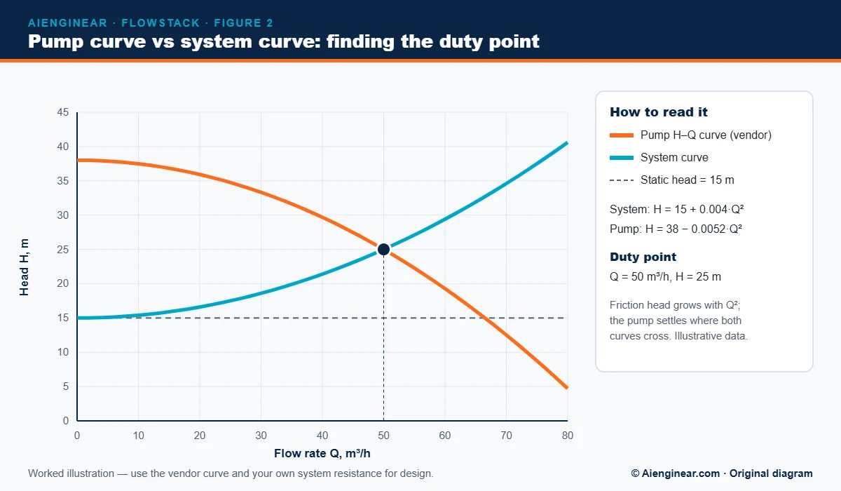
A centrifugal pump runs where its head-capacity curve crosses the system curve. The system curve is the static head plus the friction head, which rises roughly with the square of flow. Figure 2 shows the idea with simple illustrative numbers.
Cavitation is the other check. NPSH available (NPSHa) must exceed the pump’s NPSH3 — the suction head at which the vendor measured a 3 % head drop — by a margin. ANSI/HI 9.6.1 (2024 edition) gives margin guidance by application and suction energy, and API 610 (12th edition) covers centrifugal pumps for petroleum, petrochemical and natural gas service.
NPSHa = (Ps − Pv) / (ρ g) + z − hf,s

Open tank of water at 40 °C:  Ps = 101.325 kPa abs, Pv = 7.384 kPa abs, ρ = 992.2 kg/m³
Liquid level 2.0 m above impeller eye, suction losses 0.8 m

NPSHa = (101,325 − 7,384) / (992.2 × 9.81) + 2.0 − 0.8
      = 9.65 + 2.0 − 0.8 = 10.85 m
With a vendor NPSH3 of 4.5 m → margin 6.35 m, ratio 2.4
Use the Pump Sizing Calculator for total head, power and the full NPSH check, and the Compressor Power Calculator for gas service.
8. Control valves and flow meters
Control valves and flow elements are sized from the pressure drop the hydraulic design leaves for them. Give a control valve too little ΔP and it loses control authority; give it too much and you pay in pumping energy, noise or cavitation.
Aienginear FlowStack · Table 5
Control valve, meter and separator sizing references
Standards and key parameters
| Device | Reference | Key parameters | Practical note | Aienginear tool |
|---|---|---|---|---|
| Control valve | IEC 60534-2-1 (ISA-75.01.01) | Cv or Kv, choked-flow limit, FL, xT | Typical sizing target: 20 – 80 % open at normal flow | Control Valve Sizing |
| Orifice plate | ISO 5167-1 and ISO 5167-2 (2022) | C (Reader-Harris/Gallagher), ε, β | Long straight runs; β usually 0.2 – 0.75 | Orifice Plate Flow |
| Classical Venturi tube | ISO 5167-1 and ISO 5167-4 (2022) | C, ε, β, permanent loss | Low permanent pressure loss | Venturi Meter |
| Separator | API Spec 12J; Souders-Brown | K-factor, retention time, levels | Check both gas capacity and liquid residence | Two-Phase Separator |
Reviewed 17 October 2026. Typical screening values — your project design basis and company standards govern.
9. Standards behind FlowStack
Aienginear FlowStack · Table 6
Codes and references used in FlowStack
Edition status checked 17 October 2026
| Standard | Edition position | Scope |
|---|---|---|
| ISO 5167-1, -2, -4 | 2022 | Differential-pressure flow meters |
| IEC 60534-2-1 | 2011 (current) | Control valve sizing equations |
| API Std 610 | 12th edition, 2021 | Centrifugal pumps for petroleum, petrochemical and gas industries |
| ANSI/HI 9.6.1 | 2024 | NPSH margin guideline for rotodynamic pumps |
| Crane Technical Paper 410 | 2018 edition | Flow of fluids through valves, fittings and pipe |
| API RP 14E | Current API edition | Erosional velocity for offshore production piping |
| API Spec 12J | Current API edition | Oil and gas separators |
| ASME B36.10M / B36.19M | Edition per contract | Pipe dimensions and schedules |
| TEMA Standards | Edition per contract | Shell-and-tube exchanger construction |
| IAPWS-IF97 | Industrial formulation | Water and steam properties |
| NFPA 704 | Current edition | Hazard identification of materials |
Reviewed 17 October 2026. Aienginear paraphrases published methods and does not reproduce copyrighted tables. The edition named in your contract governs.
10. Common hydraulic mistakes
- Using nominal instead of inside diameter. A Schedule 80 line has a noticeably smaller bore than Schedule 40; velocity and ΔP change with D⁵.
- Taking properties at the wrong temperature. Viscosity of oils and vapour pressure of volatile liquids change sharply with temperature.
- Forgetting fittings and equipment. In short plant lines, valves, strainers and exchangers can exceed straight-pipe friction.
- Ignoring elevation. Static head often dominates, especially in two-phase risers and gravity lines.
- Leaving no NPSH margin. NPSHa equal to NPSH3 already means a 3 % head loss from cavitation.
- Sizing control valves at maximum flow only. Check minimum flow too, so the valve does not operate nearly closed.
- Treating gas lines as incompressible when the pressure drop exceeds roughly 10 % of the inlet pressure.
11. Related hubs and guides
- All 33 Aienginear engineering calculators — the full directory
- IntegriShield — Pressure Integrity & Site Safety hub — ASME VIII vessels, PSV relief, hydrotests
- MechCore — Mechanical, Energy & Documentation hub — insulation, metal weights, DocuEngine
- PSV Relief Load Calculator — protect the lines and vessels you size here
- Pipe sizes and schedules and pipe dimensions — inside diameters for hydraulic work
- Heat exchangers explained — background for exchanger sizing
- Piping specifications and components and the piping guides library
12. Frequently asked questions
What is FlowStack?
FlowStack is Aienginear’s process and hydraulics hub: 13 free browser-based calculators for fluid properties, line sizing, pressure drop, pumps, compressors, control valves, orifice and Venturi meters, separators and heat exchangers.
Which equation is used for pipe pressure drop?
Single-phase pressure drop uses the Darcy-Weisbach equation, ΔP = f(L/D)(ρv²/2), with the Darcy friction factor from Colebrook-White or an explicit form such as Churchill. Fittings use Crane TP-410 K-values or 2-K and 3-K methods.
What velocity should I use to size a liquid line?
Typical screening values are 0.6 to 1.5 m/s for pump suction and 1.5 to 3 m/s for pump discharge, with a pressure-drop budget of roughly 0.2 to 0.5 bar per 100 m on discharge lines. Your project line-sizing specification governs.
How do I calculate NPSH available?
NPSHa = (Ps − Pv)/(ρg) + z − hf,s, where Ps is the absolute pressure on the liquid surface, Pv the vapour pressure at pumping temperature, z the liquid height above the impeller eye and hf,s the suction line losses. It must exceed the vendor’s NPSH3 by a suitable margin.
Which standard is used to size control valves?
IEC 60534-2-1, which is technically equivalent to ANSI/ISA-75.01.01. It gives the Cv or Kv equations for liquid, gas and steam, including choked-flow limits.
Which standard covers orifice plates and Venturi meters?
ISO 5167, 2022 editions: Part 1 for general principles, Part 2 for orifice plates and Part 4 for Venturi tubes. The orifice discharge coefficient uses the Reader-Harris/Gallagher equation.
Are FlowStack results suitable for final design?
They are screening-grade results for feasibility, first-pass sizing and checking. Confirm final designs with the project design basis, vendor data and validated software, and have them reviewed by a qualified engineer.

Written by Muhammad Raza
Founder of Aienginear. Engineering and digital solutions professional with 26+ years managing projects, plant shutdowns and turnarounds in oil & gas, petrochemical and power generation.