Types, Principles, Applications, And Maintenance!
A heat exchanger is a device designed to transfer heat between two or more fluids. These fluids can exist in either single-phase or two-phase states, and depending on the type of heat exchanger, they may be separated or in direct contact with one another. Devices that involve energy sources, such as nuclear fuel pins or fired heaters, are typically not classified as heat exchangers, although many design principles are similar.
To effectively discuss heat exchangers, it is helpful to categorize them. There are two common approaches to classification: one based on the heat exchanger’s flow configuration, and the other on the type of equipment, primarily its construction. Both methods will be discussed here.
Classification of Heat Exchangers by Flow Configuration
Heat exchangers can generally be categorized into four basic flow configurations:
- Counter Flow
- Cocurrent Flow
- Crossflow
- Hybrid configurations, such as Cross Counterflow and Multi-Pass Flow
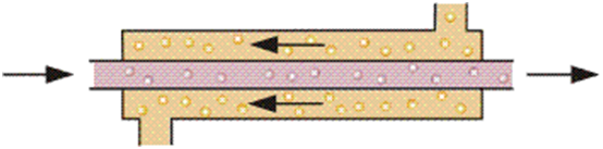
Figure 1 illustrates an idealized counterflow exchanger, where the two fluids flow parallel to each other in opposite directions. This arrangement produces the most significant temperature change in both fluids, making it the most efficient type of heat exchanger (efficiency is defined as the ratio of the actual heat transferred to the theoretical maximum heat that can be transferred).
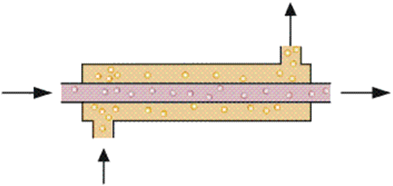
In cocurrent flow heat exchangers, the streams flow parallel to each other and in the same direction, as shown in Figure 2. This configuration is less efficient than countercurrent flow but provides more uniform wall temperatures.
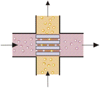
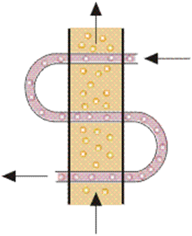
Crossflow heat exchangers offer efficiency levels between those of countercurrent and parallel-flow exchangers. In these units, the fluid streams flow at right angles to each other, as illustrated in Figure 3.
In industrial heat exchangers, hybrids of the various flow types are commonly encountered. Examples include combined crossflow/counterflow heat exchangers and multipass flow heat exchangers (see, for example, Figure 4).
Classification of Heat Exchangers by Construction
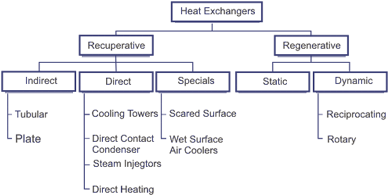
In this section, heat exchangers are primarily classified by construction, following Garland (1990) (see Figure 5). The first level of classification divides heat exchangers into two categories: recuperative and regenerative.
A Recuperative Heat Exchanger features separate flow paths for each fluid, allowing both fluids to flow simultaneously through the exchanger and exchange heat across the wall that separates the flow paths. In contrast, a Regenerative Heat Exchanger has a single flow path through which the hot and cold fluids alternately pass.
Regenerative Heat Exchangers
A regenerative heat exchanger typically contains a matrix that is heated when a hot fluid passes through it, a process referred to as the “hot blow.” This stored heat is then transferred to a cold fluid when it flows through the matrix, known as the “cold blow.” Regenerative heat exchangers are sometimes called capacitive heat exchangers. A comprehensive overview of regenerators can be found in Walker (1982).
Regenerators are primarily used in gas-to-gas heat-recovery applications, particularly in power stations and other energy-intensive industries. The two main types of regenerators are static and dynamic. Both types operate transiently, and unless meticulously designed, they may lead to cross-contamination between the hot and cold streams. However, the use of regenerators is expected to grow as efforts to enhance energy efficiency increase and more low-grade heat is recovered. Despite this, regenerative heat exchangers are typically employed for specialized applications, while recuperative heat exchangers are more commonly used.
Recuperative Heat Exchangers
There are various types of recuperative heat exchangers, which can be broadly categorized into three groups: indirect contact, direct contact, and special designs. Indirect contact heat exchangers keep the fluids exchanging heat separate by using tubes, plates, or similar structures. In contrast, direct contact exchangers do not separate the fluids; they rely on close contact between the fluids for effective heat exchange.
Heat Exchanger Types
This section briefly describes some of the more common types of heat exchangers, based on the classification presented in Figure 5.
Indirect Heat Exchangers
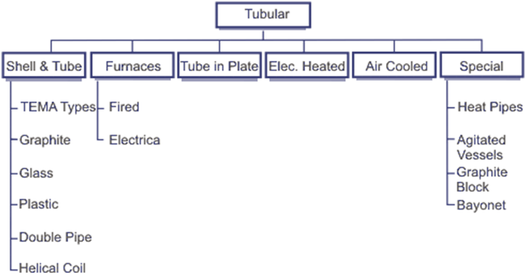
In indirect heat exchangers, the fluids are separated by a wall, typically made of metal. Common examples of these exchangers include tubular exchangers (see Figure 6) and plate exchangers (see Figure 7).
Tubular heat exchangers are particularly popular because they offer flexibility for a wide range of pressures and temperatures. This type of heat exchanger can be categorized into several types, with the shell-and-tube exchanger being the most common.
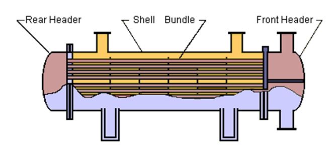
A shell-and-tube heat exchanger consists of several tubes mounted inside a cylindrical shell. As shown in Figure 8, this type of unit is commonly found in petrochemical plants. The exchanger facilitates heat transfer between two fluids: one fluid flows around the outside of the tubes, while the second fluid flows through the tubes. These fluids can be single- or two-phase and can flow in parallel or in cross/counterflow arrangements.
The shell and tube heat exchanger has four major components:
- Front End: This is where the fluid enters the tubeside of the exchanger.
- Rear End: This is where the tubeside fluid exits the exchanger or returns to the front header in exchangers with multiple tubeside passes.
- Tube Bundle: This includes the tubes, tube sheets, baffles, and tie rods that securely hold the bundle together.
- Shell: This component encases the tube bundle.
The popularity of shell-and-tube heat exchangers has led to the development of standards for their designation and use, specifically the Tubular Exchanger Manufacturers Association (TEMA) Standard. Typically, shell-and-tube exchangers are constructed from metal, but for specialized applications, such as handling strong acids or pharmaceuticals, alternative materials like graphite, plastic, and glass may be used. While it is common for the tubes to be straight, helical, or Hampson coils are sometimes employed for cryogenic applications.
A simple version of the shell-and-tube exchanger is the Double-Pipe Exchanger, which consists of one or more tubes contained within a larger pipe. In its more complex configurations, there is little distinction between a multi-tube double-pipe exchanger and a shell-and-tube exchanger. However, double pipe exchangers are generally modular in design, allowing multiple units to be bolted together to meet the required thermal duty. E.A.D. Saunders’ book (1988) offers an excellent overview of tubular exchangers.
Other types of tubular exchangers include:
- Furnaces:
- In this type, the process fluid flows through straight or helically wound tubes, with heating provided by burners or electric heaters.
- Tubes in Plate:
- Predominantly used in heat recovery and air conditioning applications, these tubes are typically mounted within a duct, where the plates serve as supports and create additional surface area through fins.
- Electrically Heated:
- In this design, fluid flows over the outside of electrically heated tubes, employing the principle of Joule Heating.
- Air-Cooled Heat Exchangers:
- These consist of a bundle of tubes, a fan system, and supporting structures. Various types of fins can be applied to the tubes to enhance the surface area on the air side. Air can be drawn through the tubes by a fan mounted above the bundle (induced draught) or pushed through by a fan mounted below (forced draught). They are ideally used in locations where obtaining sufficient cooling water is a challenge.
- Heat Pipes, Agitated Vessels, and Graphite Block Exchangers:
- These can be classified as tubular or may be categorized under Recuperative Specials.” A heat pipe comprises a pipe, wick material, and a working fluid, where the fluid absorbs heat, evaporates, travels to the other end, condenses, and releases heat. It then returns by capillary action to the hot end to re-evaporate. Agitated vessels are typically used for heating viscous fluids and consist of a vessel with tubes and an agitator, such as a propeller or a helical ribbon impeller, which ensures uniform heating. Carbon block exchangers are specifically employed when handling corrosive fluids, consisting of solid carbon blocks with drilled holes for fluid flow, fastened together with headers to form the heat exchanger.
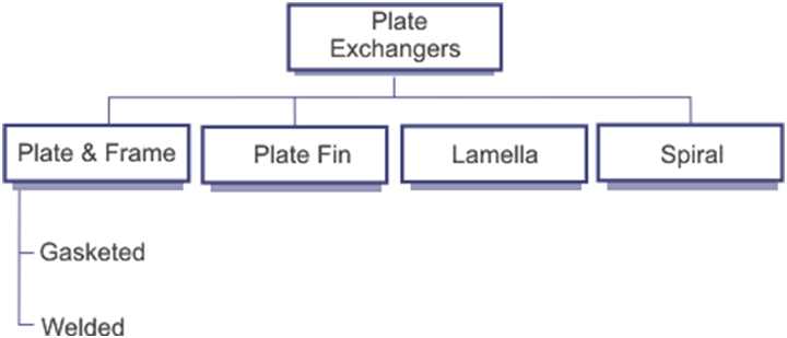
- Plate Heat Exchangers:
- These devices separate fluids by transferring heat through plates, often with enhanced surfaces such as fins or embossing, and may be bolted, brazed, or welded together. They are commonly found in the cryogenic and food processing industries. Due to their high surface area-to-volume ratio, minimal fluid inventory, and capability to handle multiple streams, they are increasingly popular in the chemical industry.
- Plate and Frame Heat Exchangers:
- This type features two rectangular end members that hold together a series of embossed rectangular plates with flow holes in the corners. Each plate is separated by a gasket that seals them and directs fluid flow between them. See Figure 9. This design is widely used in the food industry because it is easy to disassemble for cleaning. If leakage is a concern, it is possible to weld two plates together to prevent leakage between the welded sections, although some gaskets remain, which can still allow for potential leaks. Brazed plate heat exchangers eliminate the possibility of leakage by brazing all plates together and welding the inlet and outlet ports.
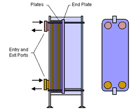
Plate Fin Exchangers consist of fins or spacers sandwiched between parallel plates. The fins can be arranged to allow for various combinations of crossflow or parallel flow between adjacent plates. With careful arrangement of headers, it is possible to pass up to 12 fluid streams through a single exchanger. These exchangers are typically made from aluminum or stainless steel and are brazed together. Their primary application is in gas liquefaction, where they can operate with close temperature approaches.
Lamella Heat Exchangers have similarities to shell-and-tube exchangers. They consist of rectangular tubes with rounded corners stacked closely together to form a bundle, which is placed inside a shell. One fluid passes through the tubes while another fluid flows in parallel through the gaps between the tubes. These exchangers are commonly used in the pulp and paper industry, where larger flow passages are required.
Spiral Plate Exchangers are created by winding two flat parallel plates together to form a coil. The ends are then sealed with gaskets or welded. These exchangers are primarily used with viscous, heavily fouling fluids or fluids containing particles or fibers.
Direct Contact Heat Exchangers do not use a heat transfer surface, making them often more economical than indirect heat exchangers. However, to use a direct contact heat exchanger with two fluids, those fluids must be immiscible. If a single fluid is used, it must undergo a phase change.
The most recognizable form of direct-contact heat exchanger is the natural-draft cooling tower found at many power stations. These units consist of a large cylindrical shell (usually over 100 meters in height) and packing at the bottom to increase surface area. Water to be cooled is sprayed onto the packing from above, while air flows in from the bottom of the packing and rises through the tower due to natural buoyancy. A significant challenge with this type of cooling tower is the continuous need to replenish the cooling water supply due to evaporation.
Direct Contact Condensers are sometimes preferred over tubular condensers because of their lower capital and maintenance costs. There are various designs of direct-contact condensers, but in its simplest form, the coolant is sprayed from the top of a vessel onto vapor entering the vessel from the side. The condensate and coolant are then collected at the bottom. The high surface area achieved by the spray ensures that these are efficient heat exchangers.
Steam Injection is used to heat fluids in tanks or pipelines. The steam enhances heat transfer through the turbulence created by the injection, and heat is transferred during condensation. Typically, no attempt is made to collect the condensate.
Direct Heating is primarily used in dryers, where a wet solid is dried by passing it through a hot air stream. Another form of direct heating is submerged combustion, which was developed mainly for the concentration and crystallization of corrosive solutions. In this method, the fluid is evaporated by directing flames and exhaust gases into the tank, where it is held.
Special Heat Exchangers: The wet-surface air cooler resembles an air-cooled heat exchanger; however, in this design, water is sprayed over the tubes, and a fan draws air and water down over the tube bundle. The entire system is enclosed, and the warm, damp air is typically vented to the atmosphere.
Scraped Surface Exchangers consist of a jacketed vessel through which the fluid passes and a rotating scraper that continuously removes deposits from the inner walls of the vessel. These units are used in the food and pharmaceutical industries for processes where deposits tend to form on the heated walls of the jacketed vessel.
Static Regenerators (or fixed bed regenerators) have no moving parts aside from valves. In this setup, hot gas flows through the matrix for a set period, after which the flow is reversed: the hot gas is shut off, and cold gas flows through the matrix. A primary challenge with this type of unit is that both hot and cold flows are intermittent. To overcome this limitation and enable continuous operation, at least two static regenerators are typically required, or a rotary regenerator can be employed.
Rotary Regenerators feature cylindrical packing that rotates around the axis of a cylinder between a pair of gas seals. Hot and cold gases flow simultaneously through ducting on either side of the gas seals and through the rotating packing.
MAINTENANCE THAT MATTERS (HIGH IMPACT)
- Inspection
- Check gaskets, tubes, baffles, and channel covers.
- Look for signs of erosion, corrosion, and fouling patterns.
- Cleaning
- Mechanical: Use brushes, rods, and hydro-jetting.
- Chemical Cleaning (CIP): Focus on scale removal and circulation cleaning.
- Pressure Testing
- Perform hydrostatic testing after reassembly.
- Ensure there is no cross-contamination or leakage.
- Tube Plugging
- Plug tubes only as a last resort.
- Map the locations and record the history of plugged tubes.
- Documentation
- Collect before-and-after fouling data.
- Use photos and a maintenance log to provide proof of reliability.
GOLDEN RULES FOR LONG EQUIPMENT LIFE
⭐ A clean heat exchanger ensures efficient plant operation.
⭐ A dirty heat exchanger leads to inefficiency. Remember, maintenance is always cheaper than reactive repairs.
A FIELD LESSON FROM EXPERIENCE
Heat exchangers rarely fail without warning. They typically provide early warning signs, such as:
- Increased pressure
- Reduced heat transfer
Maintenance is not just about fixing problems; it’s about preventing failures.