
What is an industrial pipe?
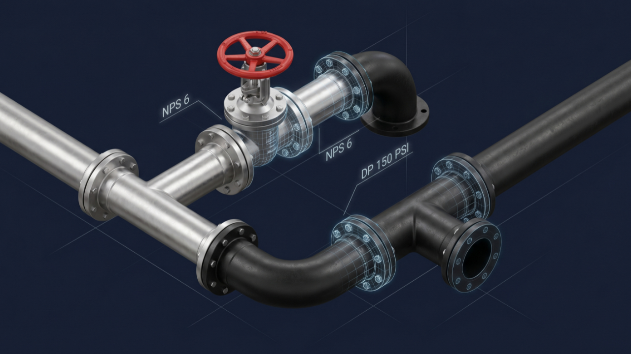
An industrial pipe is a pressure-retaining, round hollow section that carries liquids, gases, steam, slurries or powders between equipment in a plant or along a pipeline. It is identified by its Nominal Pipe Size (NPS) or Diameter Nominal (DN), a wall-thickness designation such as Schedule 40 or STD, and a material specification such as ASTM A106 Grade B or API 5L X65.
Its dimensions come from ASME B36.10M (carbon and alloy steel) or ASME B36.19 (stainless steel), while its design, wall thickness and testing are set by a piping code — most often ASME B31.3 for process plants, ASME B31.1 for power plants and EN 13480 in Europe.
1. How the piping codes define a pipe
In everyday speech a pipe is any hollow tube. In engineering it has a narrower meaning: a pipe is a pressure-tight cylinder whose size is given by a nominal designation (NPS or DN) and whose wall is given by a schedule or a specified thickness. That nominal sizing system is what lets a pipe, a flange, an elbow and a valve from different manufacturers fit together.
The codes separate the pipe (one component) from piping (the whole system). ASME B31.3 uses “piping” for the assembly of pipe, fittings, flanges, gaskets, bolting, valves, pressure-relief devices and the pipe-supporting elements that hold them. Engineers who confuse the two often under-scope inspection or stress work, because the code requirements apply to the system, not just the straight lengths.
- ASME B31.3 (Process Piping) — covers design, materials, fabrication, examination and testing of piping in petroleum refineries, chemical, pharmaceutical, LNG and similar plants.
- ASME B36.10M and B36.19 — fix the outside diameters, wall thicknesses and weights of wrought steel and stainless steel pipe for each NPS and schedule.
- API Specification 5L — covers seamless and welded steel line pipe for oil, gas, water and CO₂ transport, in two product specification levels, PSL 1 and PSL 2.
- EN 13480 — the European code for metallic industrial piping, written to support compliance with the Pressure Equipment Directive (PED) 2014/68/EU.
2. Pipe vs tube: the practical difference
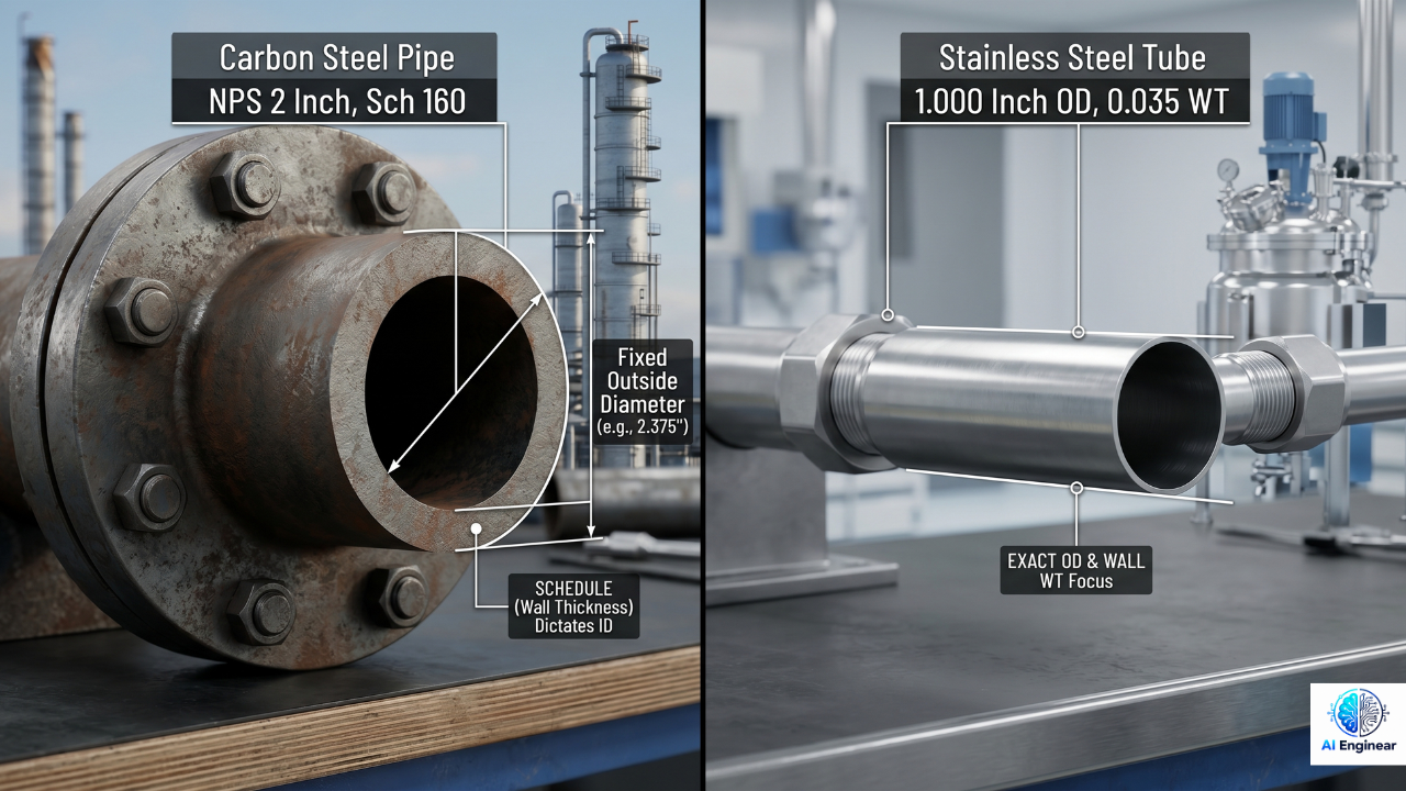
Pipes and tubes can look identical on a rack, yet they are ordered, inspected and rated in different ways. A pipe is bought by nominal size and schedule, so its inside diameter changes when the wall gets thicker. A tube is bought by its actual outside diameter and actual wall thickness (in millimetres, decimal inches or BWG gauge), with tighter dimensional tolerances. Mixing the two systems on a purchase order is one of the most common procurement errors on site.
| Attribute | Pipe | Tube |
|---|---|---|
| Size designation | Nominal: NPS (inch) or DN (mm) | Actual outside diameter (OD) |
| Wall designation | Schedule (Sch 10, 40, 80, 160), STD, XS, XXS or specified wall | Actual wall in mm / inch, or BWG gauge |
| Fixed dimension | OD fixed for each NPS; ID varies with schedule | OD and wall both fixed as ordered |
| Typical tolerances | Wall commonly −12.5 % (seamless); looser OD tolerance | Tighter OD and wall tolerances; often min-wall or average-wall ordering |
| Dimensional standards | ASME B36.10M, ASME B36.19, ISO 4200 / EN 10220, API 5L | ASTM A179, A192, A213, A249, A269, A450 / EN 10216 series |
| Main purpose | Moving fluids through plants and pipelines | Heat transfer (boilers, heat exchangers), instrumentation, hydraulics, structures |
| Typical joining | Butt-weld, socket-weld, threaded, flanged | Compression fittings, expanded or welded into tubesheets, orbital welding |
| Size range in practice | NPS ⅛ to NPS 80+ | Mostly 3 mm to about 150 mm OD |
3. Pipe sizing: NPS, DN and outside diameter
Nominal Pipe Size (NPS) is a dimensionless size label used in North America and on most international oil, gas and chemical projects. Diameter Nominal (DN), defined in ISO 6708, is the metric equivalent: DN 50 corresponds to NPS 2, DN 150 to NPS 6, and so on. Neither number is an exact measurement; both point to a fixed outside diameter listed in the dimensional standard.
- NPS ⅛ to NPS 12: the NPS number is only loosely related to the bore. The OD is fixed and larger than the NPS number — NPS 2 has a 60.3 mm (2.375 in) OD and NPS 12 has a 323.9 mm (12.750 in) OD.
- NPS 14 and larger: the OD in inches equals the NPS number — NPS 14 is 355.6 mm (14.000 in) OD and NPS 24 is 610 mm (24.000 in) OD.
- Same OD, different ID: because the OD is fixed for every schedule, a thicker wall always reduces the inside diameter. Flow calculations must use the actual ID for the schedule selected, not the NPS number.
4. Pipe schedule and wall thickness
A schedule number (Sch 5, 10, 20, 30, 40, 60, 80, 100, 120, 140, 160) is a wall-thickness designation. It is not a pressure rating and it does not give the same thickness across sizes: Sch 40 is 3.91 mm at NPS 2 but 10.31 mm at NPS 12. The older weight classes — STD (standard), XS (extra strong) and XXS (double extra strong) — are still widely used. STD matches Sch 40 up to NPS 10, and XS matches Sch 80 up to NPS 8; above those sizes they part company, so always check the table rather than assuming.
| NPS | DN | OD, mm | OD, in | Sch 40, mm | Sch 80, mm | Sch 160, mm | STD, mm | XS, mm |
|---|---|---|---|---|---|---|---|---|
| ½ | 15 | 21.3 | 0.840 | 2.77 | 3.73 | 4.78 | 2.77 | 3.73 |
| ¾ | 20 | 26.7 | 1.050 | 2.87 | 3.91 | 5.56 | 2.87 | 3.91 |
| 1 | 25 | 33.4 | 1.315 | 3.38 | 4.55 | 6.35 | 3.38 | 4.55 |
| 1½ | 40 | 48.3 | 1.900 | 3.68 | 5.08 | 7.14 | 3.68 | 5.08 |
| 2 | 50 | 60.3 | 2.375 | 3.91 | 5.54 | 8.74 | 3.91 | 5.54 |
| 3 | 80 | 88.9 | 3.500 | 5.49 | 7.62 | 11.13 | 5.49 | 7.62 |
| 4 | 100 | 114.3 | 4.500 | 6.02 | 8.56 | 13.49 | 6.02 | 8.56 |
| 6 | 150 | 168.3 | 6.625 | 7.11 | 10.97 | 18.26 | 7.11 | 10.97 |
| 8 | 200 | 219.1 | 8.625 | 8.18 | 12.70 | 23.01 | 8.18 | 12.70 |
| 10 | 250 | 273.1 | 10.750 | 9.27 | 15.09 | 28.58 | 9.27 | 12.70 |
| 12 | 300 | 323.9 | 12.750 | 10.31 | 17.48 | 33.32 | 9.53 | 12.70 |
| 14 | 350 | 355.6 | 14.000 | 11.13 | 19.05 | 35.71 | 9.53 | 12.70 |
| 16 | 400 | 406.4 | 16.000 | 12.70 | 21.44 | 40.49 | 9.53 | 12.70 |
| 18 | 450 | 457.0 | 18.000 | 14.27 | 23.83 | 45.24 | 9.53 | 12.70 |
| 20 | 500 | 508.0 | 20.000 | 15.09 | 26.19 | 50.01 | 9.53 | 12.70 |
| 24 | 600 | 610.0 | 24.000 | 17.48 | 30.96 | 59.54 | 9.53 | 12.70 |
Stainless steel pipe uses ASME B36.19, which adds the light-wall “S” schedules (Sch 5S, 10S, 40S, 80S). These are popular because corrosion-resistant alloys rarely need a corrosion allowance, so thinner walls save weight and cost. The S and non-S values are identical for most small sizes but diverge from NPS 10 upward — a frequent cause of fit-up problems when carbon steel and stainless spools meet.
| NPS | Sch 40S, mm | Sch 40, mm | Sch 80S, mm | Sch 80, mm | What to watch |
|---|---|---|---|---|---|
| 8 | 8.18 | 8.18 | 12.70 | 12.70 | Identical — interchangeable on drawings |
| 10 | 9.27 | 9.27 | 12.70 | 15.09 | 80S is 2.39 mm thinner than Sch 80 |
| 12 | 9.53 | 10.31 | 12.70 | 17.48 | Both 40S and 80S are thinner — re-check ID and bevel match |
5. Piping codes and dimensional standards (editions current in 2026)
Two kinds of document control a pipe. Design codes (the ASME B31 series, EN 13480) decide how thick the wall must be, which materials are allowed, how welds are examined and how the system is tested. Product standards (ASME B36, ASTM, API 5L) decide how the pipe itself is made and dimensioned. The code chosen is set by the facility type and the jurisdiction, not by the fluid alone.
| Document | Type | Scope | Edition (Oct 2026) |
|---|---|---|---|
| ASME B31.1 | Design code | Power piping: boilers, steam, feedwater, power and district-heating plants | 2024 |
| ASME B31.3 | Design code | Process piping: refineries, chemical, pharmaceutical, LNG, terminals | 2024 |
| ASME B31.4 | Design code | Liquid and slurry pipelines (crude, products, CO₂, ammonia) | 2025 |
| ASME B31.8 | Design code | Gas transmission and distribution pipelines | 2025 |
| ASME B31.9 | Design code | Building services piping (HVAC, utilities) | 2025 |
| ASME B31.12 | Design code | Hydrogen piping and pipelines | 2023 |
| EN 13480 (Parts 1–8) | Design code | Metallic industrial piping in Europe; Part 3 covers design and calculation | Part 3: 2024 |
| ASME B36.10M | Dimensional | Welded and seamless wrought steel pipe (carbon and alloy) | 2022 |
| ASME B36.19 | Dimensional | Welded and seamless wrought stainless steel pipe, incl. S schedules | 2022 |
| API Spec 5L | Product | Seamless and welded line pipe, PSL 1 and PSL 2, now including CO₂ transmission requirements | 47th ed., June 2026 |
| ASTM A106 / A53 / A333 / A335 / A312 | Material | Carbon, low-temperature, chrome-moly and stainless pipe | Latest ASTM year designation |
| ISO 6708 / ISO 4200 / EN 10220 | Dimensional | DN definition and metric pipe dimension series | Current ISO/EN edition |
What changed recently? ASME B31.3-2024 now points to ASME B31J for stress-intensification and sustained-stress indices, adds press-connect fittings to the listed components, allows leak-tested mechanical joints to be broken and remade without a new leak test, and adds extra guidance for ASTM A105 weld-neck flanges below −18 °C. API 5L’s 47th edition (June 2026) adds CO₂ transmission pipeline requirements and updates HFW weld quality, sour-service, impact toughness and lamination controls. For background, see our piping codes Q&A.
6. Design pressure, design temperature and corrosion allowance
Before any wall thickness is calculated, the line needs a design basis. These three values come from the process data sheet and the line list, and they drive every later decision.
- Design pressure (P): the pressure at the most severe coincident condition of pressure and temperature expected in service, including upsets such as a blocked outlet or pump shut-off. It is usually set at or above the relief-valve set pressure protecting the line. Lines that can go under vacuum also need an external-pressure check.
- Design temperature (T): the metal temperature at that coincident condition. High temperature lowers the allowable stress and can bring in creep; low temperature can make carbon steel brittle, which is why B31.3 sets minimum design metal temperatures and impact-test rules.
- Corrosion allowance (c): extra wall added to cover metal loss from corrosion and erosion over the design life. Carbon steel in hydrocarbon or water service commonly gets 1.5 mm to 3 mm; stainless and nickel alloys in clean service often get zero. Thread depth and groove depth are added to c as well.
- Fluid service category: B31.3 classifies lines as Normal, Category D, Category M (toxic), High Pressure (Chapter IX), High Purity (Chapter X) or Elevated Temperature. The category changes the examination percentage, the allowable joint types and the test method.
7. Calculating pipe wall thickness to ASME B31.3
The simple Barlow relation (P = 2St/D) is useful for a quick check, but process piping is designed to ASME B31.3 paragraph 304.1.2. For straight pipe under internal pressure, where the pressure-design thickness t is less than D/6, the code equation is:
- t — pressure-design thickness; tm — minimum required thickness including allowances
- P — internal design gauge pressure; D — outside diameter
- S — allowable stress at design temperature (B31.3 Table A-1 / A-1M)
- E — quality factor: 1.00 for seamless, 0.85 for ERW (Table A-1B)
- W — weld joint strength reduction factor: 1.0 up to 427 °C for most steels
- Y — coefficient from Table 304.1.1: 0.4 for ferritic and austenitic steels below creep range
- c — sum of corrosion, erosion, thread and groove allowances
The nominal wall you order must still meet tm after the mill under-tolerance is deducted. For seamless pipe to ASTM A106 or A53, that tolerance is −12.5 %, so the nominal wall must be at least tm ÷ 0.875. If t ≥ D/6 or P/(S·E) > 0.385, the code requires a more rigorous design that considers fatigue, failure theory and thermal stress.
| Step | Input / formula | Result |
|---|---|---|
| 1. Design data | P = 4.0 MPa (40 barg); D = 168.3 mm; S = 138 MPa; E = 1.00; W = 1.0; Y = 0.4; c = 1.5 mm | — |
| 2. Pressure-design thickness | t = 4.0 × 168.3 / [2 (138 × 1.0 × 1.0 + 4.0 × 0.4)] = 673.2 / 279.2 | 2.41 mm |
| 3. Validity check | t < D/6 = 28.1 mm and P/(SE) = 0.029 < 0.385 | Equation valid |
| 4. Minimum required thickness | tm = t + c = 2.41 + 1.5 | 3.91 mm |
| 5. Allow for mill tolerance | Nominal ≥ tm / 0.875 | 4.47 mm |
| 6. Select schedule | Lightest standard B36.10M wall ≥ 4.47 mm for NPS 6 carbon steel | Sch 40 (7.11 mm) |
| 7. Check capacity | Available t = 7.11 × 0.875 − 1.5 = 4.72 mm → P = 2 S E W t / (D − 2 Y t) | ≈ 79 barg |
Screening tool for carbon steel pipe to ASME B36.10M walls and the ASME B31.3 304.1.2 equation (internal pressure only). Default S = 138 MPa suits ASTM A106 Gr B / A53 Gr B at moderate temperature — confirm S, E, W and Y from B31.3-2024 for your material and design temperature. Not a substitute for a stamped design calculation.
Need pressure drop or line size instead? Use the pipe pressure drop calculator, the steam pipe sizing calculator or the hydrotest pressure calculator.
8. Pipe materials and where they fit
Material selection balances strength at temperature, toughness at low temperature, corrosion resistance, weldability, availability and cost. Carbon steel covers most utility and hydrocarbon lines; alloys earn their price only where the process makes carbon steel unsafe or short-lived. The temperature ranges below are typical working ranges — the code limits in B31.3 Table A-1 and the project material selection report always govern.
| Material family | Typical pipe specifications | Typical temperature range | Typical service |
|---|---|---|---|
| Carbon steel | ASTM A106 Gr B, A53 Gr B, API 5L Gr B–X70 | −29 °C to about 425 °C | Hydrocarbons, steam, cooling water, utilities, pipelines |
| Low-temperature carbon steel | ASTM A333 Gr 6 | Down to −45 °C (impact tested) | Cold hydrocarbons, flare, depressurising lines |
| Chrome-moly alloy steel | ASTM A335 P11, P22, P91 | Up to about 550–600 °C (P91 higher) | High-temperature steam, hydrogen service, fired-heater outlets |
| Austenitic stainless steel | ASTM A312 TP304/304L, TP316/316L, TP321 | −196 °C to about 540 °C | Corrosive chemicals, cryogenic LNG, food and pharma |
| Duplex and super duplex | ASTM A790 S32205, S32750 | About −50 °C to 250–300 °C | Seawater, produced water, chloride-rich process |
| Nickel alloys | ASTM B444 (625), B423 (825), B622 (C-276) | Cryogenic to above 600 °C | Sour gas, acids, severe chloride or high-temperature corrosion |
| Copper-nickel | ASTM B466 (90/10, 70/30) | Ambient to about 200 °C | Seawater cooling and firewater on marine/offshore units |
| Thermoplastics | PVC, CPVC, HDPE (PE100), PP | PVC/HDPE ≈ 60 °C; CPVC ≈ 90 °C | Water, chemical drains, buried utilities, low-pressure chemicals |
| Fibre-reinforced plastic | GRE / GRP (ISO 14692) | Typically up to 90–120 °C | Seawater, firewater, produced water, corrosive drains |
Go deeper with our guides to carbon steel piping materials, ASTM A53 pipe, alloy steel in piping, stainless steels for process piping and non-metallic piping materials.
9. How industrial pipe is manufactured
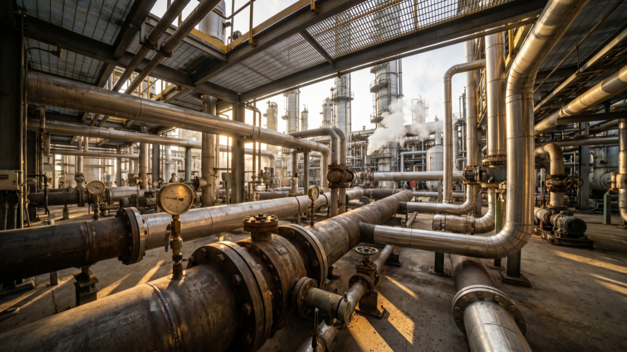
The manufacturing route matters to the designer because it sets the quality factor E in the wall-thickness equation, the size range available and the inspection the pipe receives at the mill. Seamless pipe has no longitudinal weld; welded pipe is formed from plate, strip or coil and joined along a straight or spiral seam. See the full process in our seamless pipe manufacturing guide.
| Method | How it is made | Usual size range | B31.3 factor E | Typical use |
|---|---|---|---|---|
| Seamless (SMLS) | Hot billet pierced, then elongated on a mandrel, plug or pilger mill; small sizes may be cold-drawn | NPS ⅛–24 (larger by hot expansion) | 1.00 | High pressure, high temperature, sour and cyclic service |
| ERW / HFW | Strip roll-formed and seam-welded by high-frequency resistance heating; no filler metal | NPS ½–24 | 0.85 | Utilities, low–medium pressure process, onshore line pipe |
| LSAW (UOE / JCOE) | Plate formed into a cylinder and welded along a straight seam by submerged arc, inside and outside | NPS 16–60+, heavy walls | 0.95* | Transmission pipelines, large process headers, offshore |
| HSAW (spiral) | Coil formed into a helix and submerged-arc welded along the spiral seam | NPS 20–100+ | 0.95* | Water transmission, low–medium pressure gas, piling |
| EFW (stainless / alloy) | Plate or strip formed and fusion-welded, with or without filler | NPS ⅛ and up | 0.80–1.00 | Corrosive and large-bore stainless services |
10. Pipe ends and joining methods
- Bevelled end (BE) — butt weld: the default for NPS 2 and above. ASME B16.25 sets the standard 37.5° bevel; butt welds give full strength and can be radiographed.
- Plain end (PE) — socket weld: common for NPS 1½ and smaller with ASME B16.11 fittings. Leave a 1.5 mm (1/16 in) expansion gap before welding, and avoid in crevice-corrosion or severe cyclic service.
- Threaded end (TE): NPT threads to ASME B1.20.1 for small utility lines. The thread depth must be added to the corrosion allowance; threaded joints are restricted in hazardous and cyclic services.
- Flanged joints: used where pipework must be dismantled — at equipment, valves and spool breaks. Flange class is set by ASME B16.5 (to NPS 24) or B16.47 (NPS 26–60) pressure–temperature ratings. See our ASTM A105 flange material guide.
- Mechanical joints: grooved couplings and press-connect fittings for utilities and firewater; press-connect fittings are now listed components in B31.3-2024.
11. Inspection and testing of industrial piping
Pipe is tested twice: at the mill under its product specification, and again after fabrication and erection under the piping code. The site requirements below follow ASME B31.3-2024; the project specification can add more (for example 100 % radiography or positive material identification on every alloy weld). For field methods, see our pipe inspection guide.
| Check | Requirement (summary) | Notes |
|---|---|---|
| Mill testing | Hydrostatic or NDE test, chemistry, tensile and dimensional checks per ASTM / API spec | Recorded on the mill test report (EN 10204 3.1 or 3.2) |
| Visual examination | Random sampling of materials and fabrication for Normal Fluid Service; 100 % for Category M and High Pressure | Performed by the examiner, not the welder |
| Radiography / UT of girth welds | Normal: at least 5 % random; Category M: at least 20 %; High Pressure and Severe Cyclic: 100 %; Category D: visual only | Progressive sampling applies when a defect is found |
| Hydrostatic leak test | At least 1.5 × design pressure × (ST/S), with ST/S not over 6.5; hold at least 10 minutes | Check that hoop stress stays below yield; protect against brittle fracture in cold weather |
| Pneumatic leak test | 1.1 × design pressure, only where hydrotest is impracticable | High stored energy — needs exclusion zones and owner approval |
| Sensitive leak test | Gas test at the lower of 105 kPa (15 psi) or 25 % of design pressure | Required in addition for Category M where specified |
| PMI and hardness | Positive material identification on alloy components; hardness checks after PWHT | See API RP 578 and NACE MR0175 / ISO 15156 for sour service |
12. How to select an industrial pipe, step by step
- Collect process data — fluid, phase, flow rate, operating and upset pressure and temperature, design life.
- Fix the code and fluid service category — B31.3 Normal, Category D, Category M or High Pressure; B31.1 for power boiler external piping; B31.4 or B31.8 for pipelines.
- Choose the material and corrosion allowance — check minimum design metal temperature, corrosion rate, sour (H₂S) service and cost.
- Size the line — select the NPS from allowable velocity and pressure drop, using the actual ID of the intended schedule.
- Calculate the wall and pick the schedule — apply the B31.3 equation, add allowances and mill tolerance, then choose the lightest standard wall that also suits mechanical loads, threading and handling.
- Specify joints, examination and testing — end preparation, flange class, NDE percentage, PWHT, hydrotest pressure, then record everything in the piping class (pipe spec) and line list. Add supports using the pipe support spacing calculator.
Watch: what is an industrial pipe?
Key takeaways
- A pipe is ordered by nominal size (NPS or DN) and schedule; a tube is ordered by exact OD and wall.
- The OD is fixed for each NPS — thicker schedules reduce the bore, so hydraulic calculations must use the real ID.
- From NPS 14 upward, the OD in inches equals the NPS number.
- Schedule is a wall designation, not a pressure rating; STD and Sch 40 match only up to NPS 10, and 40S/80S differ from Sch 40/80 from NPS 10 up.
- B31.3 wall thickness: t = PD / 2(SEW + PY), plus allowances, then divide by (1 − mill tolerance) before choosing a schedule.
- Check the edition: ASME B31.3-2024, B36.10M-2022, B36.19-2022 and API 5L 47th edition (2026) are current as of October 2026.
Glossary of pipe terms
- NPS (Nominal Pipe Size): North American size designation for pipe; dimensionless.
- DN (Diameter Nominal): ISO 6708 metric size designation; DN 100 ≈ NPS 4.
- Schedule (Sch): standardised wall-thickness designation within B36.10M / B36.19.
- STD / XS / XXS: standard, extra-strong and double-extra-strong weight classes.
- Mill tolerance: permitted under-thickness of the delivered wall, typically −12.5 % for seamless pipe.
- PSL 1 / PSL 2: API 5L product specification levels; PSL 2 adds mandatory toughness testing, tighter chemistry and a maximum yield strength.
- Spool: a prefabricated assembly of pipe and fittings shipped to site for erection.
- Piping class (pipe spec): project document fixing materials, ratings, wall thicknesses and components for a defined service.
Frequently asked questions about industrial pipe
What is an industrial pipe?
An industrial pipe is a pressure-retaining round hollow section used to carry liquids, gases, steam, slurries or powders through a plant or pipeline. It is identified by Nominal Pipe Size (NPS) or Diameter Nominal (DN), a wall designation such as Schedule 40 or STD, and a material specification such as ASTM A106 Grade B. Its dimensions follow ASME B36.10M or B36.19 and its design follows a piping code such as ASME B31.3.
What is the difference between a pipe and a tube?
A pipe is specified by nominal size (NPS or DN) and schedule, so its outside diameter is fixed and its inside diameter changes with wall thickness; it is used mainly to move fluids. A tube is specified by its exact outside diameter and wall thickness, has tighter tolerances and is used for heat exchangers, boilers, instrumentation and structures.
Does NPS equal the outside diameter of a pipe?
Only from NPS 14 upward, where the OD in inches equals the NPS number (NPS 14 = 14.000 in / 355.6 mm). From NPS 1/8 to NPS 12 the OD is larger than the NPS number; for example NPS 2 has a 2.375 in (60.3 mm) OD and NPS 6 has a 6.625 in (168.3 mm) OD.
What is the difference between DN and NPS?
NPS is the inch-based North American size designation and DN is the metric designation defined in ISO 6708. They describe the same pipe: DN 15 = NPS 1/2, DN 50 = NPS 2, DN 100 = NPS 4, DN 150 = NPS 6 and DN 600 = NPS 24. Neither is an exact measured diameter.
Is Schedule 40 the same as STD?
Schedule 40 and STD (standard weight) have the same wall thickness from NPS 1/8 to NPS 10. From NPS 12 upward STD stays at 9.53 mm (0.375 in) while Schedule 40 becomes thicker, for example 10.31 mm at NPS 12. Always state the actual wall or the exact designation on drawings and purchase orders.
How is the minimum pipe wall thickness calculated under ASME B31.3?
ASME B31.3 paragraph 304.1.2 gives the pressure-design thickness t = PD / 2(SEW + PY), valid when t is less than D/6. Add corrosion, erosion and thread allowances to get the minimum required thickness tm = t + c, then divide by (1 − mill under-tolerance), typically 0.875 for seamless pipe, and select the next standard schedule at or above that value.
When should ASME B31.1 be used instead of ASME B31.3?
ASME B31.1 Power Piping is used for power plants, boiler external piping, steam and feedwater systems and district heating. ASME B31.3 Process Piping is used for refineries, chemical, pharmaceutical, LNG and similar process plants. The owner and the jurisdiction decide the code; within one facility different systems can fall under different codes.
What corrosion allowance is typical for carbon steel pipe?
Carbon steel lines in hydrocarbon, water or steam service are commonly given a corrosion allowance of 1.5 mm (1/16 in) to 3 mm (1/8 in), chosen from the expected corrosion rate multiplied by the design life. Stainless steel and nickel alloys in clean service are often given zero corrosion allowance. The project piping class sets the final value.
What is the hydrostatic test pressure for process piping?
Under ASME B31.3 the hydrostatic leak test pressure is at least 1.5 times the design pressure, multiplied by the ratio of allowable stress at test temperature to allowable stress at design temperature (ratio not more than 6.5). The pressure is held for at least 10 minutes and must not cause hoop stress above yield.
What is the latest edition of API 5L?
API Specification 5L, Line Pipe, 47th Edition was published in June 2026. It adds requirements for carbon dioxide transmission pipelines and updates HFW weld quality, sour service, impact toughness, lamination control and non-destructive testing personnel requirements. It keeps two product specification levels, PSL 1 and PSL 2.
Test your knowledge: industrial pipe quiz
Loading quiz…
Related Aienginear guides and tools
- Pipe sizes and schedule chart — full B36.10M / B36.19 tables
- Pipe materials guide and pipe material types and selection
- Piping colour codes and identification standards
- 50 piping interview questions and answers
Disclaimer: This guide is for education and preliminary engineering. Code values are summarised from ASME B31.3-2024, ASME B36.10M-2022, ASME B36.19-2022, API Spec 5L 47th Edition and EN 13480-3:2024; always work from the licensed standard and the edition specified for your project. © Aienginear — aienginear.com