
What is ASTM A105?
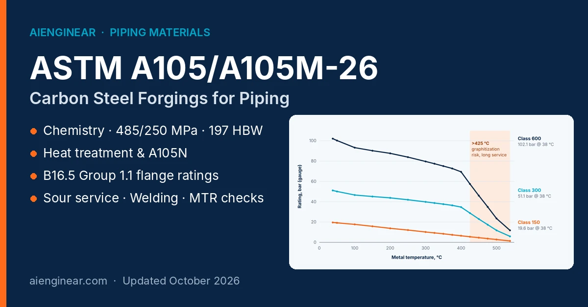
ASTM A105/A105M is the ASTM material specification for forged carbon-steel piping components — mainly flanges, forged fittings and valve parts — used in pressure systems at ambient and elevated temperatures. It limits carbon to 0.35 %, requires 485 MPa (70 ksi) minimum tensile and 250 MPa (36 ksi) minimum yield strength, caps hardness at 197 HBW, and sets heat-treatment, testing and marking rules. The current edition is A105/A105M-26. It controls the material only; dimensions and pressure ratings come from component standards such as ASME B16.5.
1. What ASTM A105 covers — and what it doesn’t
ASTM A105 applies to forged carbon-steel parts that sit inside a piping system and carry pressure: flanges, forged fittings, valve bodies, bonnets and similar components. Parts can be made to the purchaser’s own drawing or to a published dimensional standard from ASME, MSS or API.
Four scope limits are worth memorising:
- Mass cap. A single A105 forging may not exceed 10,000 lb (4,540 kg). Heavier pieces are normally ordered to ASTM A266/A266M.
- Exclusions. Tubesheets and hollow cylindrical forgings for pressure-vessel shells fall outside the scope, even though they are carbon-steel forgings.
- Bar and tube. Some small parts may be machined from hot-rolled or forged bar or from seamless tube under the conditions the specification sets out. The bar or tube stock itself is not an A105 product.
- Units. Inch-pound values apply unless the order calls for “A105M”. Each unit system is standard in its own right — choose one and use it consistently on the PO, MTR and drawings.
2. How ASTM A105 fits with codes and component standards
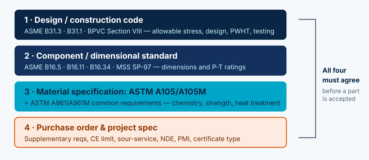
A compliant ASTM A105 flange is the product of four documents working together. The design code decides whether the material is permitted and at what allowable stress; the component standard fixes geometry and pressure rating; ASTM A105 — together with the common requirements of ASTM A961/A961M — fixes the steel; and the purchase order adds whatever extra the project needs.
3. ASTM A105 products and their dimensional standards
| Product | Dimensional / rating standard | Notes |
|---|---|---|
| Weld-neck, slip-on, blind, socket-weld, threaded and lap-joint flanges, NPS ½–24 | ASME B16.5 | Material Group 1.1; Classes 150–2500 |
| Large-diameter flanges, NPS 26–60 | ASME B16.47 (Series A / B) | Confirm the series selected for the project |
| Socket-weld and threaded fittings (elbows, tees, couplings, caps) | ASME B16.11; MSS SP-83 (unions) | Classes 2000, 3000, 6000, 9000 |
| Branch outlet fittings (weldolets, sockolets, threadolets) | MSS SP-97 | Rating tied to the run-pipe schedule |
| Valve bodies, bonnets, end connections | ASME B16.34; API 600 / 602 / 6D as applicable | Heat-treatment triggers often apply (NPS > 4 and Class > 300) |
| Orifice flanges, spectacle blinds, special forgings | ASME B16.36, B16.48 or purchaser drawing | Special designs follow the drawing and PO |
Always use the edition named in your contract. ASME B16.5 and B16.34 were both reissued in 2025.
Typical industries include oil and gas production, refineries, petrochemical and fertilizer plants, power stations (steam, feedwater and auxiliary systems), cement plants and general utilities — anywhere non-corrosive or mildly corrosive fluids run at ambient to elevated temperature. For fitting geometry, see our guide to pipe fittings dimensions and materials.
4. How A105 forgings are made
ASTM A105 starts as killed steel — steel deoxidised with silicon and/or aluminium so it solidifies without gas porosity. Forging then refines the grain and makes the grain flow follow the part’s contour, which is why a forged flange outperforms one cut from plate.
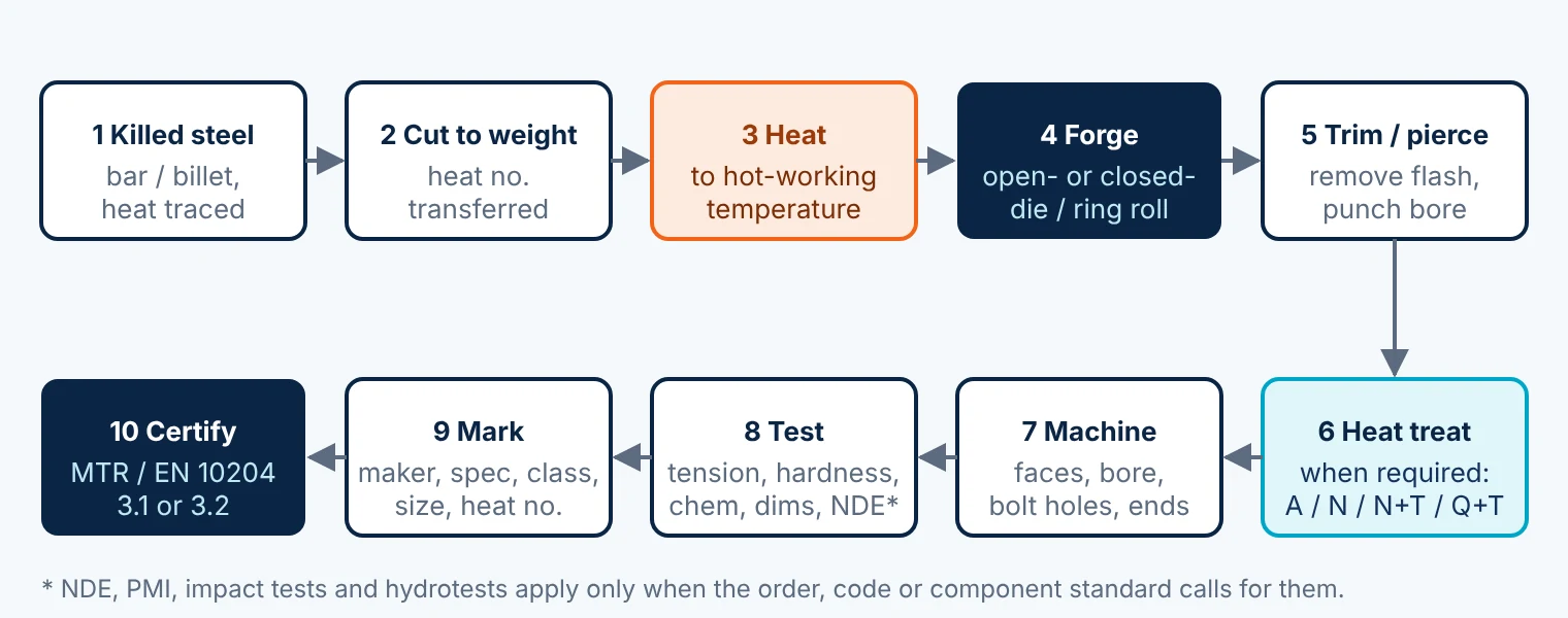
- Stock preparation. Bar, billet or bloom is cut to the calculated forging weight, and the heat number is transferred to every piece.
- Hot working. Small fittings are usually closed-die forged; flanges are open-die forged, upset, or ring-rolled in larger sizes.
- Finishing. Flash is trimmed and bores pierced, then faces, bores, bolt holes and weld bevels are machined.
- Heat treatment (when required). Annealing, normalizing, normalizing + tempering, or quenching + tempering.
- Testing, marking and certification. Tension and hardness tests, chemical analysis, dimensional checks and any purchaser-specified NDE, followed by marking and issue of the mill test report (MTR).
Weld repair of ASTM A105 forgings is allowed only under the specification’s conditions and, where required, with purchaser approval. If your PO restricts weld repair, ask for the repair records.
5. ASTM A105 chemical composition and carbon equivalent
| Element | Limit, % | Why it matters |
|---|---|---|
| Carbon (C) | 0.35 max | Main strength contributor; more C means harder welding |
| Manganese (Mn) | 0.60 – 1.05 a | Strength and hardenability; ties up sulfur |
| Phosphorus (P) | 0.035 max | Impurity — embrittles |
| Sulfur (S) | 0.040 max | Impurity — hot shortness, lamination risk |
| Silicon (Si) | 0.10 – 0.35 | Deoxidiser (killed steel) |
| Copper (Cu) | 0.40 max b | Residual element |
| Nickel (Ni) | 0.40 max b | Residual element |
| Chromium (Cr) | 0.30 max b, c | Residual element |
| Molybdenum (Mo) | 0.12 max b, c | Residual element |
| Vanadium (V) | 0.08 max b | Residual element |
a For each 0.01 % that carbon falls below 0.35 %, manganese may rise 0.06 % above 1.05 %, up to an absolute ceiling of 1.35 %. b Cu + Ni + Cr + Mo + V ≤ 1.00 %. c Cr + Mo ≤ 0.32 %. Intentionally leaded steel is not permitted. Product (check) analysis tolerances follow ASTM A961/A961M.
Worked example: the manganese allowance
Heat analysis: C = 0.30 %
Carbon below max   = 0.35 − 0.30   = 0.05 %  → 5 steps of 0.01 %
Extra Mn permitted = 5 × 0.06      = 0.30 %
Mn ceiling         = 1.05 + 0.30    = 1.35 %  ✔ (exactly at the cap)

Heat analysis: C = 0.25 %
Calculated ceiling = 1.05 + 10 × 0.06 = 1.65 %
Applied ceiling    = 1.35 %  ← the absolute cap governs
Carbon equivalent (CE) for weldability
ASTM A105 sets no CE limit by default, but a carbon-equivalent maximum can be invoked as a supplementary requirement on the order, and many owner specifications set their own, stricter value. Calculate CE from the MTR with the IIW formula:
CE (IIW) = C + Mn/6 + (Cr + Mo + V)/5 + (Ni + Cu)/15

Example MTR: C 0.20  Mn 1.00  Cr 0.10  Mo 0.02  V 0.01  Ni 0.10  Cu 0.15
CE = 0.20 + 0.167 + 0.026 + 0.017 = 0.41
A CE of roughly 0.40–0.45 is generally comfortable for welding with low-hydrogen practice; as CE rises, preheat and hardness control matter more. If you need a CE limit, put it on the PO — don’t assume the mill will apply one. The free checker in Section 6 calculates CE for you.
6. Free A105 tools: flange rating finder and MTR chemistry checker
Use these two calculators to size a flange class and to screen a mill test report before you accept material. They run in your browser — nothing is uploaded.
Ratings: ASME B16.5 Material Group 1.1 (bar gauge), linear interpolation between tabulated temperatures. For education and preliminary sizing — confirm against the B16.5 edition in your contract.
Enter the heat analysis from the mill test report (mass %). Leave an element blank if it is not reported — the checker will flag it.
Limits: ASTM A105/A105M heat analysis. A screening aid only — product-analysis tolerances (ASTM A961), supplementary requirements and your PO still apply.
7. ASTM A105 mechanical properties and testing
| Property | SI | US customary | Basis / comment |
|---|---|---|---|
| Tensile strength, min | 485 MPa | 70 ksi | All forgings |
| Yield strength, min | 250 MPa | 36 ksi | All forgings |
| Elongation, min — strip specimen | 30 % | 30 % | 50 mm (2 in.) gauge, wall ≥ 7.9 mm (5/16 in.); deductions apply to thinner walls |
| Elongation, min — round specimen | 22 % | 22 % | Standard 12.5 mm (0.500 in.) round, gauge length = 4D |
| Reduction of area, min | 30 % | 30 % | Round specimens |
| Hardness, max | 197 HBW | 197 HBW | Brinell; no specification minimum |
Testing in practice. Tension specimens come from a production forging or from a representative test bar of the same heat, processed in the same heat-treatment charge. Hardness is checked on the forgings themselves at the frequency required by A105 and ASTM A961. Forgings must be capable of passing a hydrostatic test at the rating of their component standard; a shop hydrotest is actually carried out only when the component standard or the PO calls for one. ASTM A105 has no default Charpy impact test — add one through the order if the design code or service requires it.
Under ASME B31.3, the basic allowable stress at ambient temperature is governed by one-third of the minimum tensile strength — about 161 MPa (23.3 ksi). For design, always take values from the code’s own stress table, not from this summary.
8. A105 heat treatment and A105N
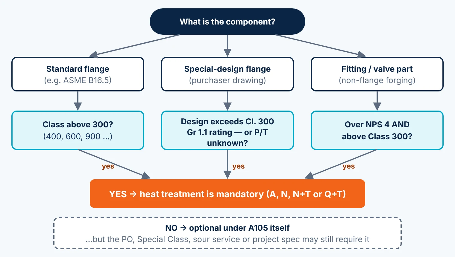
Many ASTM A105 forgings may be supplied as-forged. Heat treatment becomes mandatory under the specification for:
- flanges above Class 300;
- special-design flanges whose design pressure at design temperature exceeds the Class 300 rating for Group 1.1 materials;
- special-design flanges where the design pressure or design temperature is not known;
- non-flange components (fittings, valve parts) that are both larger than NPS 4 and above Class 300;
- Special Class components as defined in ASME B16.34, under that standard’s additional criteria.
| Route | What happens | Typical use |
|---|---|---|
| Annealing (A) | Heat above the transformation range, then cool slowly in the furnace | Softest condition; good machinability |
| Normalizing (N) | Heat above the upper critical temperature (roughly 870–925 °C for this grade) and cool in still air | Most common; refines grain and evens out toughness |
| Normalizing + tempering (N+T) | Normalize, then reheat below the lower critical temperature | Relieves stress and lowers hardness after normalizing |
| Quenching + tempering (Q+T) | Austenitize, quench in liquid, then temper at ≥ 590 °C (1100 °F) | Heavier sections, extra strength margin |
What does “A105N” mean?
“A105N” is an industry marking convention, not a separate ASTM grade. It signals that the forging was normalized. Many project specifications require normalizing for every A105 part regardless of size or class, because normalized forgings have a more uniform microstructure, more predictable hardness and better toughness. If you need it, write “normalized” on the PO and check that the MTR records the heat-treatment temperature, soak time and cooling medium.
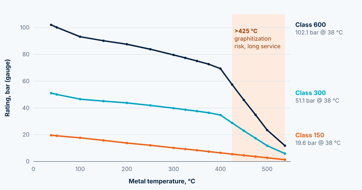
9. A105 flange pressure-temperature ratings (ASME B16.5, Group 1.1)
ASTM A105 belongs to ASME B16.5 Material Group 1.1, alongside materials such as A216 WCB castings, A350 LF2 forgings and A515/A516 Grade 70 plate. A flange’s allowable working pressure falls as metal temperature rises:
| Temp, °C | Class 150 | 300 | 600 | 900 | 1500 | 2500 |
|---|---|---|---|---|---|---|
| −29 to 38 | 19.6 | 51.1 | 102.1 | 153.2 | 255.3 | 425.5 |
| 100 | 17.7 | 46.6 | 93.2 | 139.8 | 233.0 | 388.3 |
| 150 | 15.8 | 45.1 | 90.2 | 135.2 | 225.4 | 375.6 |
| 200 | 13.8 | 43.8 | 87.6 | 131.4 | 219.0 | 365.0 |
| 250 | 12.1 | 41.9 | 83.9 | 125.8 | 209.7 | 349.5 |
| 300 | 10.2 | 39.8 | 79.6 | 119.5 | 199.1 | 331.8 |
| 350 | 8.4 | 37.6 | 75.1 | 112.7 | 187.8 | 313.0 |
| 400 | 6.5 | 34.7 | 69.4 | 104.2 | 173.6 | 289.3 |
| 425 | 5.5 | 28.8 | 57.5 | 86.3 | 143.8 | 239.7 |
| 450 | 4.6 | 23.0 | 46.0 | 69.0 | 115.0 | 191.7 |
| 500 | 2.8 | 11.8 | 23.5 | 35.3 | 58.8 | 97.9 |
| 538 | 1.4 | 5.9 | 11.8 | 17.7 | 29.5 | 49.2 |
Inch-pound ratings at −20 to 100 °F: Class 150 = 285 psig, 300 = 740, 600 = 1,480, 900 = 2,220, 1500 = 3,705, 2500 = 6,170. Values are as published in recent B16.5 editions; confirm them against the edition named in your contract (B16.5-2025 is current) and interpolate linearly only as B16.5 permits. Joint tightness also depends on the gasket, bolting and assembly — see our gasket and flange-face guide.
How to use the table: take the maximum design temperature, read across, and pick the lowest class whose rating meets or exceeds the design pressure. Example: 30 barg at 250 °C needs Class 300 (41.9 bar), because Class 150 gives only 12.1 bar. The rating finder above does this interpolation for you.
10. Temperature limits and sour service
Low temperature
ASTM A105 carries no mandatory impact test, so its usual lower limit without impact testing is −29 °C (−20 °F). Below that — or wherever the code’s impact-exemption rules are not met — specify ASTM A350 LF2 (Class 1, impact-tested to −46 °C) or another impact-tested grade. Confirm the minimum design metal temperature (MDMT) and the governing code’s exemption curves before you choose A105.
High temperature
B16.5 ratings for A105 run up to 538 °C, but carbon steel held above about 425 °C for long periods can convert its carbide phase to graphite, which weakens the steel. Use A105 above 425 °C only for short-term or intermittent service. For continuous creep-range duty, move up to a Cr-Mo grade such as A182 F11 or F22.
Sour (H₂S) service
- NACE MR0175 / ISO 15156-2 (oil and gas production): carbon steels are generally acceptable up to 22 HRC (about 237 HBW) with additional conditions on welds and heat treatment. For A105 forgings, many operators and EPC specifications tighten this to 187 HBW maximum — the limit must be written on the order, because it is stricter than the 197 HBW base limit.
- NACE MR0103 / ISO 17945 (refining and related processes): A105 forgings are expected to be supplied heat treated (annealed, normalized, N+T or Q+T) and hardness-controlled, typically to 187 HBW maximum. An as-forged part cannot be shown to comply.
- Owners often add HIC/SSC testing, lower sulfur limits or weld-hardness limits. Treat these as PO items and confirm them against the edition of the standard your project invokes.
11. Welding A105: P-Number, preheat and PWHT
For welding qualification, SA-105 is classed as ASME Section IX P-No. 1, Group No. 2. That lets most carbon-steel procedures qualified on P-No. 1 base metals cover A105-to-pipe joints such as A105 to A106 Grade B.
- Preheat follows the construction code and WPS. Thick flanges and high-CE heats benefit from preheat even where it is not mandatory.
- PWHT for P-No. 1 materials is thickness-driven. Under ASME B31.3, for example, it is required above a governing thickness of 19 mm (¾ in.), typically at 595–650 °C. B31.1 and BPVC Section VIII have their own rules — follow the governing code.
- Socket-weld fittings (B16.11) need an approximately 1.6 mm (1/16 in.) expansion gap before welding to prevent root cracking.
12. ASTM A105 vs. A350 LF2, A181, A694, A182, A266 and A234
| Specification | Product form | Key difference from A105 | Choose it when… |
|---|---|---|---|
| A105 | Carbon-steel piping forgings | — | Ambient / elevated temperature, non-severe service |
| A350 LF2 | Carbon-steel forgings, low temperature | Mandatory Charpy impact testing (Class 1: −46 °C) | MDMT below −29 °C |
| A181 | General-purpose carbon-steel forgings | Lower requirements; Class 60 / 70; limited code acceptance | Non-critical, low-pressure utility service |
| A694 F42–F70 | High-yield forgings for transmission service | Specified yield strength up to 485 MPa (70 ksi) | Matching high-strength API 5L line pipe |
| A182 F11 / F22 | Alloy (Cr-Mo) forgings | Creep and graphitization resistance | Long-term service above ~425 °C |
| A182 F304 / F316 | Stainless forgings | Corrosion resistance, cryogenic toughness | Corrosive or very cold service |
| A266 | Carbon-steel vessel forgings | No 10,000 lb mass limit; vessel components | Heavy forgings, nozzles, vessel parts |
| A234 WPB | Wrought butt-weld fittings | Made from pipe or plate, not forged blanks | Butt-weld elbows, tees, reducers (B16.9) |
| A106 Gr B | Seamless pipe | Pipe, not a forging | The pipe A105 flanges usually mate with |
For a wider comparison of carbon-steel grades, see carbon steel piping materials, ASTM A53 pipe and pipe material selection. For high-temperature alternatives, read alloy steel in piping.
13. Reading A105 markings and the mill test report
Markings are stamped, die-stamped or stencilled on each ASTM A105 forging, usually on the flange rim or the fitting body. A typical sequence looks like this:
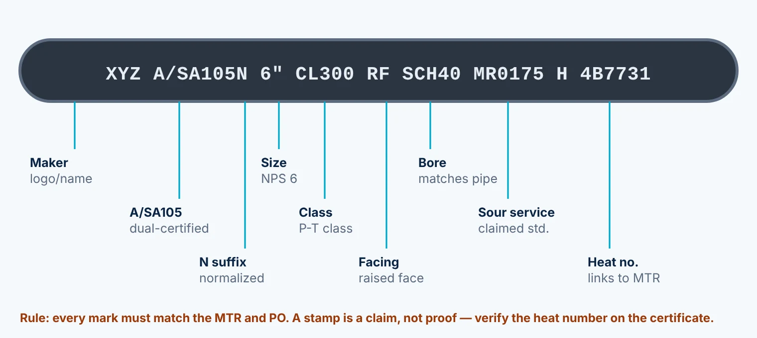
“A/SA105” means the forging is dual-certified to ASTM A105 and ASME SA-105 (the adoption in ASME BPVC Section II). On the MTR, check that:
- the specification and edition match the PO (for example “ASTM A105/A105M-26”, or the edition you accepted);
- the heat number on the MTR matches the stamp on the part;
- the chemistry lists every element in the table above, and the Mn allowance, the residual-sum rule and the Cr + Mo rule all pass;
- tensile, yield, elongation (with specimen type stated), reduction of area and hardness are all reported;
- heat treatment is recorded with temperature, time and cooling medium — or “as-forged” where that is permitted;
- the certificate type (for example EN 10204 3.1 or 3.2) is the one you ordered.
14. A105 purchasing and receiving checklist
- Specification and edition — “ASTM A105/A105M-26” or the edition your code accepts; dual A/SA-105 for ASME-stamped work.
- Component definition — type, NPS, class, facing, bore/schedule and the dimensional standard with its edition.
- Service conditions — design pressure and temperature, MDMT, fluid and corrosion allowance, so the supplier can flag limits.
- Heat treatment — state “normalized” if the project specification requires it, even where A105 makes it optional.
- Supplementary requirements — CE limit, impact tests, extra hardness tests and NDE (UT/MT) as needed.
- Sour service — invoke MR0175/ISO 15156 or MR0103/ISO 17945 explicitly, with a 187 HBW maximum hardness.
- Documentation — MTR type, heat-treatment charts, PMI records and dimensional reports.
- Receiving inspection — visual and dimensional check, marking vs MTR vs PO, spot hardness or PMI where required.
- Quarantine discrepancies — any unmatched heat number or missing data: hold, raise an NCR, do not install.
15. Common mistakes to avoid
- Treating A105 as a design standard. It gives no ratings or dimensions; pair it with B16.5, B16.11 or B16.34.
- Using A105 below −29 °C. Without impact testing it is not qualified for low-temperature service — use A350 LF2.
- Quoting 187 HBW as the A105 limit. The base limit is 197 HBW; 187 HBW is a sour-service requirement you must order.
- Assuming every forging is heat treated. Small, low-class parts may be as-forged. Specify normalizing if you need it.
- Confusing A105 with A106 or A234. A105 covers forgings, A106 seamless pipe, A234 wrought butt-weld fittings.
- Applying the Mn allowance without the cap. Manganese never exceeds 1.35 %, whatever the carbon content.
- Mixing SI and inch-pound values. Order A105 or A105M and keep every document in the same unit system.
- Trusting the stamp alone. Counterfeit and mis-marked fittings exist. Always reconcile the heat number with the MTR, and consider PMI for critical systems.
16. ASTM A105 FAQs
What is ASTM A105 material?
ASTM A105 is a forged carbon steel (C ≤ 0.35 %) specified for piping components such as flanges, forged fittings and valve parts in ambient- and elevated-temperature pressure service. It requires at least 485 MPa (70 ksi) tensile strength, 250 MPa (36 ksi) yield strength and a maximum hardness of 197 HBW.
What is the difference between A105 and A105N?
The material is identical. "N" is a marking convention showing that the forging was normalized. ASTM does not list A105N as a separate grade, so specify normalizing on the purchase order if your project requires it.
What is the maximum hardness of ASTM A105?
The current specification limits hardness to 197 HBW. For sour service, most project specifications and NACE MR0103/ISO 17945 practice cap A105 at 187 HBW, and that limit must be stated on the order.
What is the minimum temperature for ASTM A105?
Without impact testing, A105 is normally limited to −29 °C (−20 °F). For colder service, use ASTM A350 LF2 or another impact-tested material, as the governing code allows.
Is ASTM A105 the same as ASME SA-105?
SA-105 is the ASME adoption of A105 in BPVC Section II Part A. The two are technically aligned, but ASME may adopt a different edition year. For code-stamped work the material must meet the edition ASME accepts; dual-certified "A/SA105" forgings satisfy both.
Does every A105 forging need heat treatment?
No. Heat treatment is mandatory for flanges above Class 300, for certain special-design flanges, and for fittings or valve parts that are both larger than NPS 4 and above Class 300. Otherwise it is optional unless the PO, project specification or a sour-service standard requires it.
What is the pressure rating of an A105 Class 150 flange?
Under ASME B16.5 Group 1.1, a Class 150 A105 flange is rated 19.6 bar (285 psig) from −29 °C to 38 °C, falling to 13.8 bar at 200 °C and 6.5 bar at 400 °C.
Can A105 be used above 425 °C?
B16.5 ratings extend to 538 °C, but prolonged exposure above about 425 °C can cause graphitization in carbon steel. For continuous high-temperature service, choose a Cr-Mo forging such as A182 F11 or F22.
What is the maximum weight of an A105 forging?
10,000 lb (4,540 kg) per forging. Heavier forgings are normally ordered to ASTM A266/A266M.
What is the P-Number of A105?
SA-105 is P-No. 1, Group No. 2 in ASME Section IX, so it is covered by most carbon-steel welding procedures qualified on P-No. 1 base metals.
What is the current edition of ASTM A105?
ASTM A105/A105M-26, published in 2026, which replaced the 2024 edition. Always use the edition named in the contract or accepted by the governing code.
Related Aienginear tools and guides
- Piping Specification & Component Calculator — build component lists by class and material
- Hydrotest & Pressure Test Calculator — test pressures for flanged systems
- Pipe Support Spacing Calculator — span limits for carbon-steel lines
- Steam Pipe Sizing Calculator — size steam lines that use A105 flanges
- Types of Pipe Fittings — where forged fittings fit in
- ASTM A53 Pipe Guide — the companion pipe specification
- Piping Materials Interview Questions — test your A105 knowledge
References
- ASTM International, ASTM A105/A105M-26, Standard Specification for Carbon Steel Forgings for Piping Applications.
- ASTM A961/A961M, Common Requirements for Steel Flanges, Forged Fittings, Valves, and Parts for Piping Applications (edition per contract).
- ASME, B16.5-2025, Pipe Flanges and Flanged Fittings: NPS ½ Through NPS 24; ASME B16.11, Forged Fittings, Socket-Welding and Threaded; ASME B16.34-2025, Valves — Flanged, Threaded, and Welding End.
- ASME B31.3, Process Piping; ASME BPVC Section II Part A (SA-105) and Section IX.
- NACE MR0175/ISO 15156 and NACE MR0103/ISO 17945, materials for H₂S-containing environments.
- ASTM A350/A350M, A181/A181M, A694/A694M, A182/A182M and A266/A266M — companion forging specifications.

Written by Muhammad Raza
Founder of Aienginear. Engineering and digital solutions professional with 26+ years managing projects, plant shutdowns and turnarounds in oil & gas, petrochemical and power generation.