
Quick answer
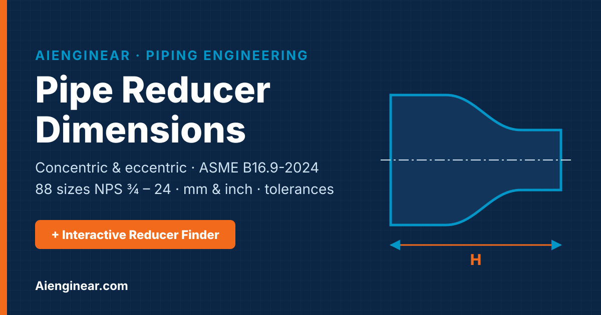
Pipe reducer dimensions are defined by three values: the outside diameter at the bevel of the large end (D₁), the outside diameter at the bevel of the small end (D₂) and the end-to-end length (H). For example, an NPS 6 × 4 reducer has D₁ = 168.3 mm, D₂ = 114.3 mm and H = 140 mm (5.50 in) according to ASME B16.9-2024. The same H applies to both concentric and eccentric reducers.
Key takeaways
- A pipe reducer is a butt-weld fitting that joins two different pipe sizes; its length H depends only on the large-end NPS.
- Concentric reducers keep one common centreline; eccentric reducers keep one side flat and shift the centreline by about e = (D₁ − D₂)/2.
- Dimensions for wrought steel reducers NPS ½ – 48 are governed by ASME B16.9-2024 – the current edition, published 16 October 2024.
- Concentric and eccentric reducers of the same size have the same H; reducer H tolerance is ±2 mm up to NPS 24 and ±5 mm for NPS 26 – 48.
- On horizontal pump suction, an eccentric reducer is normally installed flat on top (FOT) so that no air or vapour pocket can form.
What is a pipe reducer?
A pipe reducer is a short conical fitting with one large and one small butt-welding end. It provides a smooth, welded transition between two nominal pipe sizes in the same line – for example where a header steps down to a branch size, where a line must match an equipment nozzle, or where a control valve is smaller than the pipe it sits in. Because the bore changes, the reducer also changes the flow velocity, so its type, position and orientation affect hydraulics, drainage, venting and pipe-rack elevations, not only the fit-up.
In plant language a reducer used to go from small to large in the flow direction is still called a reducer – the fitting is the same, only the installation direction changes. Butt-weld reducers made from wrought steel to ASME B16.9 are the most common type in process plants (see our overview of types of pipe fittings), power stations, refineries, fertilizer and cement plants, and water and utility systems.
Concentric vs eccentric reducer
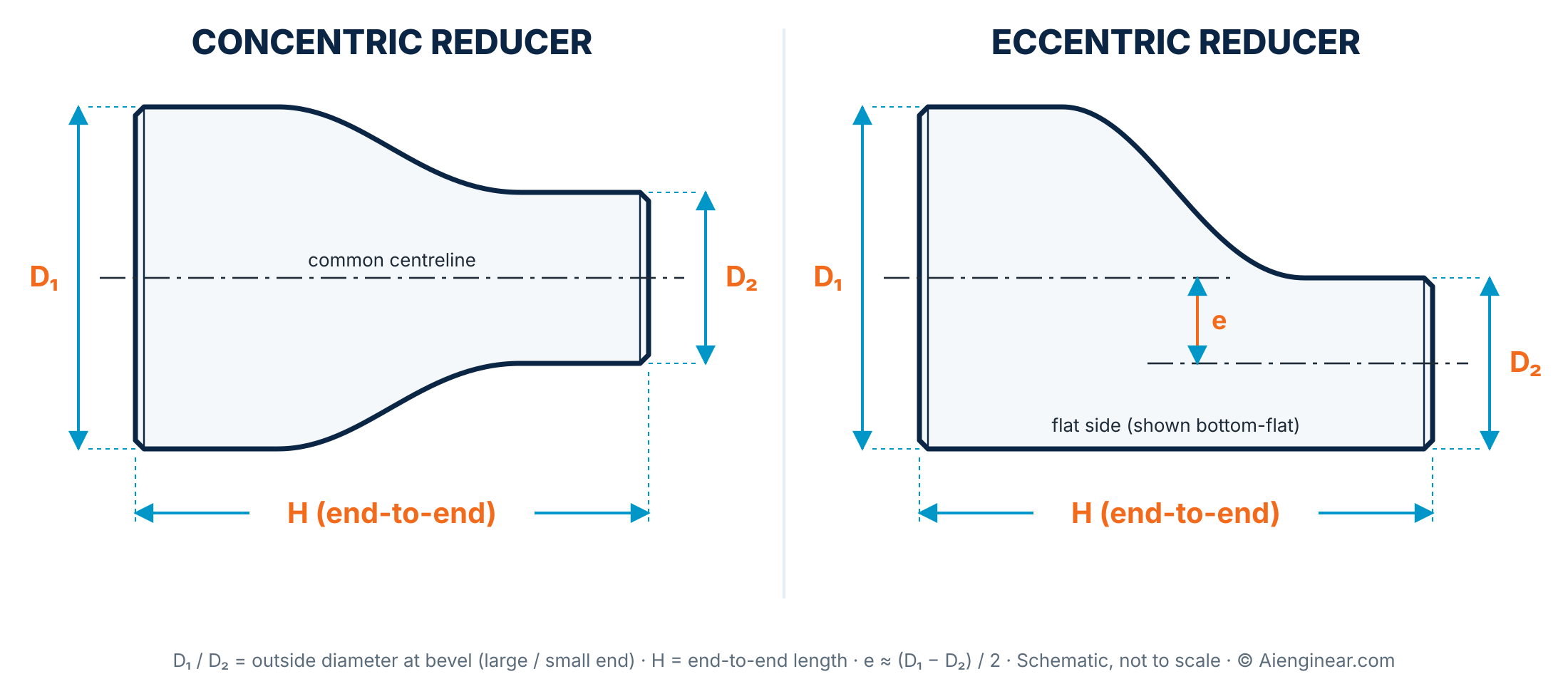
A concentric reducer narrows symmetrically around one shared centreline, like a cone. An eccentric reducer has one straight side that runs the full length of the fitting, so the centreline of the small end is shifted from the centreline of the large end. The flat side can be installed on top (FOT) or on the bottom (FOB), and that choice is a design decision that must be shown on the isometric.
| Feature | Concentric reducer | Eccentric reducer |
|---|---|---|
| Centrelines | One common centreline | Offset by e ≈ (D₁ − D₂)/2 |
| Shape | Symmetrical cone | One flat side, one sloped side |
| End-to-end length H | Per ASME B16.9 table | Same H as concentric of same size |
| Typical use | Vertical lines, pump discharge, compressor and fan nozzles, places where centreline elevation is kept | Horizontal pump suction (FOT), pipe racks (FOB keeps bottom-of-pipe), drain-sensitive and steam/condensate lines (FOB) |
| Main risk if misapplied | Air pocket at the crown or liquid pocket at the invert in horizontal lines | Wrong orientation (FOT/FOB) creates the pocket it was meant to prevent |
| What to state on the PO | Size, schedule of each end, material, standard | Same as concentric, plus FOT/FOB shown on isometric |
Basis: ASME B16.9-2024 and common plant layout practice. Compiled by Aienginear — aienginear.com/pipe-reducer-dimensions/
Where each reducer type is used
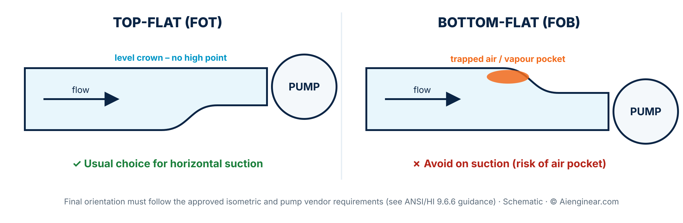
- Horizontal pump suction: eccentric, flat on top. A level crown stops air or vapour from collecting upstream of the pump nozzle, which helps protect NPSH margin and avoids cavitation-like noise. Hydraulic Institute guidance (ANSI/HI 9.6.6) supports this arrangement; the pump vendor’s requirements govern. Check suction velocity and NPSH margin with the pump sizing and NPSH calculator.
- Pump discharge and vertical lines: concentric is normal because the centreline is kept and no pocket can form in a vertical run.
- Pipe racks and sleepers: eccentric flat on bottom keeps a constant bottom-of-pipe (BOP) elevation so the line sits on the same support steel without shims.
- Steam, condensate and drainable lines: eccentric flat on bottom keeps the invert continuous so condensate or liquid drains forward instead of collecting at a step. Size the line first with the steam pipe sizing calculator.
- Slurry and solids-bearing lines: flat on bottom is often used so solids are not trapped at a low step.
- Control valve and meter runs: concentric reducers are common on each side of a reduced-bore valve; follow the valve vendor and project standards for straight lengths.
Reducer dimension symbols explained
| Symbol | Meaning | Practical note |
|---|---|---|
| NPS | Nominal Pipe Size (inch designation) | A size name, not a measured diameter – NPS 4 has an OD of 114.3 mm |
| DN | Nominal diameter (metric designation) | DN 100 = NPS 4; also not a measured size |
| D₁ | Outside diameter at bevel, large end | Matches the OD of the large connecting pipe |
| D₂ | Outside diameter at bevel, small end | Matches the OD of the small connecting pipe |
| H | End-to-end length (face to face) | Set by the large-end NPS; the same for concentric and eccentric |
| e | Eccentric offset between centrelines | ≈ (D₁ − D₂)/2 for equal wall; use (ID₁ − ID₂)/2 for exact flat-side alignment |
| t₁, t₂ | Wall thickness at each end | Specified by the purchaser to match the pipe schedule at each end |
| Bevel | Weld end preparation | Per ASME B16.25 unless the project specifies otherwise |
Terminology per ASME B16.9-2024, ASME B16.25 and ISO 6708 (DN). Compiled by Aienginear — aienginear.com/pipe-reducer-dimensions/
Across the NPS ¾ – 24 range of ASME B16.9, the reducer length H changes only when the large-end size changes. Every NPS 8 reducer is 152 mm long, whether it is 8 × 6 or 8 × 3½. If you know H for one combination, you know it for all combinations with that large end.
Interactive Reducer Finder
Velocity and ID values use nominal walls; the eccentric offset by ID is the exact flat-side alignment value. Verify against the manufacturer’s drawing.
Pipe reducer dimensions chart – NPS ¾ to 24 (ASME B16.9-2024)
The chart below lists 88 standard concentric and eccentric reducer size combinations with outside diameters at the bevel and end-to-end length in both millimetres and inches. Use the search box to filter by size (for example type 6 × or DN 150), switch units, then use Print or Copy in the table header (they follow the current filter and unit) or download the full chart as CSV.
| NPS large × small | DN | D₁ OD large end | D₂ OD small end | H end-to-end | e ecc. offset* |
|---|---|---|---|---|---|
| ¾ × ½ | 20 × 15 | 26.71.05 | 21.30.84 | 381.50 | 2.70.11 |
| ¾ × ⅜ | 20 × 10 | 26.71.05 | 17.30.68 | 381.50 | 4.70.18 |
| 1 × ¾ | 25 × 20 | 33.41.32 | 26.71.05 | 512.00 | 3.30.14 |
| 1 × ½ | 25 × 15 | 33.41.32 | 21.30.84 | 512.00 | 6.00.24 |
| 1¼ × 1 | 32 × 25 | 42.21.66 | 33.41.32 | 512.00 | 4.40.17 |
| 1¼ × ¾ | 32 × 20 | 42.21.66 | 26.71.05 | 512.00 | 7.80.30 |
| 1¼ × ½ | 32 × 15 | 42.21.66 | 21.30.84 | 512.00 | 10.50.41 |
| 1½ × 1¼ | 40 × 32 | 48.31.90 | 42.21.66 | 642.50 | 3.00.12 |
| 1½ × 1 | 40 × 25 | 48.31.90 | 33.41.32 | 642.50 | 7.40.29 |
| 1½ × ¾ | 40 × 20 | 48.31.90 | 26.71.05 | 642.50 | 10.80.42 |
| 1½ × ½ | 40 × 15 | 48.31.90 | 21.30.84 | 642.50 | 13.50.53 |
| 2 × 1½ | 50 × 40 | 60.32.38 | 48.31.90 | 763.00 | 6.00.24 |
| 2 × 1¼ | 50 × 32 | 60.32.38 | 42.21.66 | 763.00 | 9.00.36 |
| 2 × 1 | 50 × 25 | 60.32.38 | 33.41.32 | 763.00 | 13.40.53 |
| 2 × ¾ | 50 × 20 | 60.32.38 | 26.71.05 | 763.00 | 16.80.66 |
| 2½ × 2 | 65 × 50 | 73.02.88 | 60.32.38 | 893.50 | 6.40.25 |
| 2½ × 1½ | 65 × 40 | 73.02.88 | 48.31.90 | 893.50 | 12.40.49 |
| 2½ × 1¼ | 65 × 32 | 73.02.88 | 42.21.66 | 893.50 | 15.40.61 |
| 2½ × 1 | 65 × 25 | 73.02.88 | 33.41.32 | 893.50 | 19.80.78 |
| 3 × 2½ | 80 × 65 | 88.93.50 | 73.02.88 | 893.50 | 8.00.31 |
| 3 × 2 | 80 × 50 | 88.93.50 | 60.32.38 | 893.50 | 14.30.56 |
| 3 × 1½ | 80 × 40 | 88.93.50 | 48.31.90 | 893.50 | 20.30.80 |
| 3 × 1¼ | 80 × 32 | 88.93.50 | 42.21.66 | 893.50 | 23.40.92 |
| 3½ × 3 | 90 × 80 | 101.64.00 | 88.93.50 | 1024.00 | 6.30.25 |
| 3½ × 2½ | 90 × 65 | 101.64.00 | 73.02.88 | 1024.00 | 14.30.56 |
| 3½ × 2 | 90 × 50 | 101.64.00 | 60.32.38 | 1024.00 | 20.60.81 |
| 3½ × 1½ | 90 × 40 | 101.64.00 | 48.31.90 | 1024.00 | 26.61.05 |
| 3½ × 1¼ | 90 × 32 | 101.64.00 | 42.21.66 | 1024.00 | 29.71.17 |
| 4 × 3½ | 100 × 90 | 114.34.50 | 101.64.00 | 1024.00 | 6.40.25 |
| 4 × 3 | 100 × 80 | 114.34.50 | 88.93.50 | 1024.00 | 12.70.50 |
| 4 × 2½ | 100 × 65 | 114.34.50 | 73.02.88 | 1024.00 | 20.60.81 |
| 4 × 2 | 100 × 50 | 114.34.50 | 60.32.38 | 1024.00 | 27.01.06 |
| 4 × 1½ | 100 × 40 | 114.34.50 | 48.31.90 | 1024.00 | 33.01.30 |
| 5 × 4 | 125 × 100 | 141.35.56 | 114.34.50 | 1275.00 | 13.50.53 |
| 5 × 3½ | 125 × 90 | 141.35.56 | 101.64.00 | 1275.00 | 19.90.78 |
| 5 × 3 | 125 × 80 | 141.35.56 | 88.93.50 | 1275.00 | 26.21.03 |
| 5 × 2½ | 125 × 65 | 141.35.56 | 73.02.88 | 1275.00 | 34.21.34 |
| 5 × 2 | 125 × 50 | 141.35.56 | 60.32.38 | 1275.00 | 40.51.59 |
| 6 × 5 | 150 × 125 | 168.36.62 | 141.35.56 | 1405.50 | 13.50.53 |
| 6 × 4 | 150 × 100 | 168.36.62 | 114.34.50 | 1405.50 | 27.01.06 |
| 6 × 3½ | 150 × 90 | 168.36.62 | 101.64.00 | 1405.50 | 33.41.31 |
| 6 × 3 | 150 × 80 | 168.36.62 | 88.93.50 | 1405.50 | 39.71.56 |
| 6 × 2½ | 150 × 65 | 168.36.62 | 73.02.88 | 1405.50 | 47.71.87 |
| 8 × 6 | 200 × 150 | 219.18.62 | 168.36.62 | 1526.00 | 25.41.00 |
| 8 × 5 | 200 × 125 | 219.18.62 | 141.35.56 | 1526.00 | 38.91.53 |
| 8 × 4 | 200 × 100 | 219.18.62 | 114.34.50 | 1526.00 | 52.42.06 |
| 8 × 3½ | 200 × 90 | 219.18.62 | 101.64.00 | 1526.00 | 58.82.31 |
| 10 × 8 | 250 × 200 | 273.010.75 | 219.18.62 | 1787.00 | 27.01.07 |
| 10 × 6 | 250 × 150 | 273.010.75 | 168.36.62 | 1787.00 | 52.32.06 |
| 10 × 5 | 250 × 125 | 273.010.75 | 141.35.56 | 1787.00 | 65.82.60 |
| 10 × 4 | 250 × 100 | 273.010.75 | 114.34.50 | 1787.00 | 79.33.12 |
| 12 × 10 | 300 × 250 | 323.812.75 | 273.010.75 | 2038.00 | 25.41.00 |
| 12 × 8 | 300 × 200 | 323.812.75 | 219.18.62 | 2038.00 | 52.42.07 |
| 12 × 6 | 300 × 150 | 323.812.75 | 168.36.62 | 2038.00 | 77.83.06 |
| 12 × 5 | 300 × 125 | 323.812.75 | 141.35.56 | 2038.00 | 91.23.60 |
| 14 × 12 | 350 × 300 | 355.614.00 | 323.812.75 | 33013.00 | 15.90.62 |
| 14 × 10 | 350 × 250 | 355.614.00 | 273.010.75 | 33013.00 | 41.31.62 |
| 14 × 8 | 350 × 200 | 355.614.00 | 219.18.62 | 33013.00 | 68.32.69 |
| 14 × 6 | 350 × 150 | 355.614.00 | 168.36.62 | 33013.00 | 93.73.69 |
| 16 × 14 | 400 × 350 | 406.416.00 | 355.614.00 | 35614.00 | 25.41.00 |
| 16 × 12 | 400 × 300 | 406.416.00 | 323.812.75 | 35614.00 | 41.31.62 |
| 16 × 10 | 400 × 250 | 406.416.00 | 273.010.75 | 35614.00 | 66.72.62 |
| 16 × 8 | 400 × 200 | 406.416.00 | 219.18.62 | 35614.00 | 93.63.69 |
| 16 × 6 | 400 × 150 | 406.416.00 | 168.36.62 | 35614.00 | 119.04.69 |
| 18 × 16 | 450 × 400 | 457.018.00 | 406.416.00 | 38115.00 | 25.31.00 |
| 18 × 14 | 450 × 350 | 457.018.00 | 355.614.00 | 38115.00 | 50.72.00 |
| 18 × 12 | 450 × 300 | 457.018.00 | 323.812.75 | 38115.00 | 66.62.62 |
| 18 × 10 | 450 × 250 | 457.018.00 | 273.010.75 | 38115.00 | 92.03.62 |
| 18 × 8 | 450 × 200 | 457.018.00 | 219.18.62 | 38115.00 | 119.04.69 |
| 20 × 18 | 500 × 450 | 508.020.00 | 457.018.00 | 50820.00 | 25.51.00 |
| 20 × 16 | 500 × 400 | 508.020.00 | 406.416.00 | 50820.00 | 50.82.00 |
| 20 × 14 | 500 × 350 | 508.020.00 | 355.614.00 | 50820.00 | 76.23.00 |
| 20 × 12 | 500 × 300 | 508.020.00 | 323.812.75 | 50820.00 | 92.13.62 |
| 20 × 10 | 500 × 250 | 508.020.00 | 273.010.75 | 50820.00 | 117.54.62 |
| 20 × 8 | 500 × 200 | 508.020.00 | 219.18.62 | 50820.00 | 144.45.69 |
| 22 × 20 | 550 × 500 | 559.022.00 | 508.020.00 | 50820.00 | 25.51.00 |
| 22 × 18 | 550 × 450 | 559.022.00 | 457.018.00 | 50820.00 | 51.02.00 |
| 22 × 16 | 550 × 400 | 559.022.00 | 406.416.00 | 50820.00 | 76.33.00 |
| 22 × 14 | 550 × 350 | 559.022.00 | 355.614.00 | 50820.00 | 101.74.00 |
| 22 × 12 | 550 × 300 | 559.022.00 | 323.812.75 | 50820.00 | 117.64.62 |
| 22 × 10 | 550 × 250 | 559.022.00 | 273.010.75 | 50820.00 | 143.05.62 |
| 24 × 22 | 600 × 550 | 610.024.00 | 559.022.00 | 50820.00 | 25.51.00 |
| 24 × 20 | 600 × 500 | 610.024.00 | 508.020.00 | 50820.00 | 51.02.00 |
| 24 × 18 | 600 × 450 | 610.024.00 | 457.018.00 | 50820.00 | 76.53.00 |
| 24 × 16 | 600 × 400 | 610.024.00 | 406.416.00 | 50820.00 | 101.84.00 |
| 24 × 14 | 600 × 350 | 610.024.00 | 355.614.00 | 50820.00 | 127.25.00 |
| 24 × 12 | 600 × 300 | 610.024.00 | 323.812.75 | 50820.00 | 143.15.62 |
| 24 × 10 | 600 × 250 | 610.024.00 | 273.010.75 | 50820.00 | 168.56.62 |
Showing 88 of 88 sizes. *e = (D₁ − D₂)/2, equal-wall approximation. Source basis: ASME B16.9-2024 · Compiled by Aienginear.com
Dimensional basis: ASME B16.9-2024 (Table for concentric and eccentric reducers). Compiled by Aienginear — aienginear.com/pipe-reducer-dimensions/
- Values are for factory-made wrought butt-welding reducers to ASME B16.9-2024; the same H applies to concentric and eccentric types.
- OD values are outside diameters at the bevel. ASME B16.9 rounds NPS 10 and NPS 12 to 273.0 mm and 323.8 mm; pipe tables in ASME B36.10M show 273.1 mm and 323.9 mm – the difference is rounding only.
- Use one unit system throughout a calculation. Inch values are those listed in the standard, not exact conversions of the mm values.
- Combinations not listed here (and sizes NPS 26 – 48) must be confirmed against the licensed standard or the manufacturer’s drawing.
- Stainless light-wall reducers (Sch 5S/10S) made to MSS SP-43 share these dimensions up to NPS 24, except for the OD-at-bevel tolerance.
Worked example: NPS 8 × 6 eccentric reducer
A cooling-water line steps down from NPS 8 to NPS 6 STD on a pipe rack and later on a pump suction. The example shows how the chart values turn into the numbers a piping designer, a support engineer and a site inspector actually use.
| Step | Formula / input | Result |
|---|---|---|
| 1. Chart values | NPS 8 × 6 (DN 200 × 150): D₁ = 219.1 mm, D₂ = 168.3 mm | H = 152 mm (6.00 in) |
| 2. Offset by OD | e = (219.1 − 168.3) / 2 | 25.4 mm |
| 3. Bore at each end | ID₁ = 219.1 − 2 × 8.18; ID₂ = 168.3 − 2 × 7.11 (STD walls, ASME B36.10M) | 202.7 mm / 154.1 mm |
| 4. Offset by ID | e = (202.7 − 154.1) / 2 – use for exact flat-side alignment | 24.3 mm |
| 5. Velocity change | v₂ / v₁ = (ID₁ / ID₂)² | 1.73 × (2.0 m/s becomes about 3.5 m/s) |
| 6. FOB on a pipe rack | Bottom of pipe stays level; centreline drops by e, top of pipe drops by D₁ − D₂ | CL −25.4 mm, TOP −50.8 mm, no shim |
| 7. FOT on pump suction | Top of pipe stays level; bottom of pipe rises by D₁ − D₂ | Support under the 6″ side +50.8 mm |
| 8. Fit-up check | H tolerance ±2 mm (NPS ½ – 24); OD tolerance by end NPS | Accept H between 150 and 154 mm |
Chart values: ASME B16.9-2024; wall thickness: ASME B36.10M-2022 STD. Compiled by Aienginear — aienginear.com/pipe-reducer-dimensions/
On a rack the FOB reducer keeps every shoe on the same steel, but the pipe top steps down by 50.8 mm – check clashes with cable trays or other lines above. On pump suction the FOT reducer keeps the crown level, so the pipe support nearest the pump must be set 50.8 mm higher than the one under the 8″ line. Space those supports with the pipe support spacing calculator.
ASME B16.9 dimensional tolerances for reducers
ASME B16.9 sets tolerances by NPS band. For reducers, four of them matter: the outside diameter at the bevel, the inside diameter at the end, the wall thickness and the overall length H. OD and ID tolerances apply to each end according to that end’s NPS; the H tolerance follows the reducer size band. Tolerances are plus and minus unless shown otherwise.
| NPS | DN | OD at bevel | ID at end | Wall thickness | Overall length H |
|---|---|---|---|---|---|
| ½ – 2½ | 15 – 65 | +1.6 / −0.8+0.06 / −0.03 | ±0.8±0.03 | ≥ 87.5 % of nominal | ±2±0.06 |
| 3 – 3½ | 80 – 90 | ±1.6±0.06 | ±1.6±0.06 | ≥ 87.5 % of nominal | ±2±0.06 |
| 4 | 100 | ±1.6±0.06 | ±1.6±0.06 | ≥ 87.5 % of nominal | ±2±0.06 |
| 5 – 8 | 125 – 200 | +2.4 / −1.6+0.09 / −0.06 | ±1.6±0.06 | ≥ 87.5 % of nominal | ±2±0.06 |
| 10 – 18 | 250 – 450 | +4.0 / −3.2+0.16 / −0.12 | ±3.2±0.12 | ≥ 87.5 % of nominal | ±2±0.09 |
| 20 – 24 | 500 – 600 | +6.4 / −4.8+0.25 / −0.19 | ±4.8±0.19 | ≥ 87.5 % of nominal | ±2±0.09 |
| 26 – 30 | 650 – 750 | +6.4 / −4.8+0.25 / −0.19 | +6.4 / −4.8+0.25 / −0.19 | ≥ 87.5 % of nominal | ±5±0.19 |
| 32 – 48 | 800 – 1200 | +6.4 / −4.8+0.25 / −0.19 | +6.4 / −4.8+0.25 / −0.19 | ≥ 87.5 % of nominal | ±5±0.19 |
Tolerances per ASME B16.9-2024; follows the unit switch above the dimension chart. Compiled by Aienginear — aienginear.com/pipe-reducer-dimensions/
- Wall thickness at any point must not be less than 87.5 % of the nominal thickness, except where the standard allows otherwise for formed areas.
- Out-of-roundness is the sum of the absolute plus and minus OD tolerance values.
- The purchaser specifies the nominal wall thickness (or schedule) at each end; the ID tolerance applies to the nominal ID, i.e. nominal OD minus twice the nominal wall.
- The SI values shown are those used in the SI edition of the standard; do not mix them with the inch column in one check.
Pressure rating and wall thickness
ASME B16.9 does not publish pressure–temperature tables for reducers. Instead, a fitting made to the standard is rated the same as straight seamless pipe of equivalent material with the wall thickness or schedule ordered for its ends. In practice this means a reducer is as strong as the matching pipe, provided the material grade and end thicknesses match the pipe and the design is checked under the governing code (for example ASME B31.3 for process piping, B31.1 for power piping or B31.4/B31.8 for pipelines).
- Each end can have a different schedule – for example 6 × 4 Sch 40 × Sch 80. State both on the purchase order and check walls in the pipe sizes and schedule chart.
- If the pipe is thicker than the fitting (or vice versa), the transition at the weld must follow ASME B16.25 and the piping code – typically a taper of not steeper than 1:4 (about 14°) on the thicker part.
- ASME B16.9 states that choosing the material and confirming fitness for the service conditions is the user’s responsibility, not the standard’s.
Materials and related standards
| Standard / grade | What it covers | Typical reducer use |
|---|---|---|
| ASTM A234 WPB / WPC | Carbon steel wrought fittings, moderate and high temperature | Water, steam, oil, utilities, general process |
| ASTM A234 WP11 / WP22 / WP91 | Chromium-molybdenum alloy fittings | High-temperature steam and refinery service |
| ASTM A420 WPL6 | Carbon steel fittings for low-temperature service | Cryogenic-adjacent and cold service down to about −46 °C (impact tested) |
| ASTM A403 WP304/304L/316/316L (-S, -W, -WX) | Austenitic stainless steel fittings | Chemicals, food, pharma, corrosive water |
| ASTM A815 (duplex) | Ferritic/austenitic stainless fittings | Seawater, chlorides, offshore |
| ASTM B366 | Nickel and nickel-alloy fittings | Severe corrosion and high temperature |
| ASME B16.9-2024 | Dimensions, tolerances, ratings, testing and marking | Governs reducer geometry, NPS ½ – 48 |
| MSS SP-43 | Light-wall stainless butt-weld fittings | Sch 5S / 10S stainless systems |
| MSS SP-75 | High-strength wrought butt-weld fittings (WPHY grades) | Pipeline reducers matched to API 5L X-grade line pipe |
| MSS SP-95 | Swage nipples and bull plugs | Small-bore reductions with plain, bevelled or threaded ends |
| ASME B16.11 | Forged socket-weld and threaded fittings | Small-bore reducing inserts and couplings (typically NPS 2 and below) |
| EN 10253-2 / -4 | European butt-welding fittings (carbon / austenitic steel) | Metric projects; reducer lengths can differ from ASME – do not mix tables |
| ASME B16.25-2022 | Butt-welding end preparation | Bevel angle, root face, transitions |
| ASME B36.10M-2022 / B36.19-2022 | Carbon/alloy and stainless pipe dimensions | OD and wall thickness of connecting pipe |
Editions checked against ASME, ASTM and MSS publication records, November 2026. The edition named in your contract governs. Compiled by Aienginear — aienginear.com/pipe-reducer-dimensions/
How to specify or order a pipe reducer
- Type: concentric, or eccentric with FOT/FOB shown on the isometric.
- Size: large-end × small-end NPS (and DN if the project uses DN).
- Wall thickness at each end: schedule or thickness in mm, e.g. Sch 40 × Sch 80.
- Material: full ASTM specification and grade, e.g. ASTM A234 WPB (seamless or welded construction if it matters).
- Standard and edition: ASME B16.9-2024 (or the edition named in the contract).
- Ends: butt-weld bevel per ASME B16.25, or special prep if the WPS requires it.
- Service data: design pressure and temperature, corrosion allowance, NACE/sour-service or impact-test requirements.
- Documents: EN 10204 3.1 material certificate, marking, dimensional report and any third-party inspection.
Reducer, concentric, BW, NPS 6 × 4 (DN 150 × 100), Sch 40 × Sch 40, ASTM A234 WPB seamless, dimensions to ASME B16.9-2024, bevel to ASME B16.25, MTC to EN 10204 3.1. – The Reducer Finder above builds this line for you.
Receiving inspection and installation checklist
- Follow the full method in our pipe fittings inspection guide; the reducer-specific points are below.
- Check marking: manufacturer, material grade, schedule/thickness, size and the ASME B16.9 symbol or reference.
- Measure D₁, D₂ and H and compare with the chart and the tolerance band; check out-of-roundness at both ends.
- Check the wall at each end against the ordered schedule (minimum 87.5 % of nominal).
- Inspect bevels for angle, root face, laminations and damage; protect them until fit-up.
- Match heat numbers on the reducer to the material certificate for traceability.
- For eccentric reducers, confirm FOT/FOB against the isometric before tack welding – a reversed eccentric is a common site error.
- Confirm supports near the reducer, especially at pump nozzles, so that nozzle loads stay within the vendor’s limits.
Common mistakes to avoid
- Taking NPS as the actual outside diameter (NPS 6 is 168.3 mm OD, not 152.4 mm).
- Assuming eccentric reducers are longer than concentric ones – the standard H is the same.
- Ordering by size only and leaving out the schedule of each end.
- Installing an eccentric reducer flat-on-bottom on pump suction, creating an air pocket.
- Using a concentric reducer in a horizontal steam or drain line where condensate will pond at the step.
- Mixing mm and inch values from different tables in one dimensional check.
- Quoting an old edition (B16.9-2018 or earlier) on new purchase orders without a project reason.
- Using H tolerance for OD or ID checks – each dimension has its own tolerance column.
Frequently asked questions
What are the dimensions of a 6 × 4 reducer?
An NPS 6 × 4 butt-weld reducer to ASME B16.9 has a large-end OD of 168.3 mm (6.62 in), a small-end OD of 114.3 mm (4.50 in) and an end-to-end length H of 140 mm (5.50 in). The dimensions are the same for concentric and eccentric types.
What is the difference between a concentric and an eccentric reducer?
A concentric reducer is symmetrical about one centreline. An eccentric reducer has one flat side, so the centrelines of its two ends are offset by roughly half the difference between the two outside diameters.
Which standard covers pipe reducer dimensions?
ASME B16.9 covers factory-made wrought butt-welding reducers from NPS ½ to NPS 48. The current edition is ASME B16.9-2024. MSS SP-43 covers light-wall stainless fittings, and ASME B16.11 covers forged socket-weld and threaded fittings.
Is the length of an eccentric reducer the same as a concentric reducer?
Yes. ASME B16.9 gives one end-to-end length H for each reducer size, and it applies to both concentric and eccentric reducers.
How do you calculate the offset of an eccentric reducer?
For equal wall thickness at both ends, the offset is e = (D₁ − D₂) / 2. For an NPS 6 × 4 reducer that is (168.3 − 114.3) / 2 = 27 mm. If the end walls differ, use the inside diameters instead: e = (ID₁ − ID₂) / 2.
Why is an eccentric reducer installed flat on top on pump suction?
With the flat side on top, the crown of the line stays level, so there is no high point where air or vapour can collect before the pump. A trapped pocket can reduce available NPSH and cause noisy, unstable operation.
What is the tolerance on reducer length H?
Under ASME B16.9 the overall length H of a reducer has a tolerance of ±2 mm (±0.06 in up to NPS 8, ±0.09 in for NPS 10 – 24) and ±5 mm (±0.19 in) for NPS 26 – 48.
Does NPS equal the outside diameter of a reducer?
Only from NPS 14 upward. Below NPS 14 the outside diameter is larger than the nominal size – for example NPS 2 is 60.3 mm and NPS 4 is 114.3 mm.
Can a reducer have different schedules at each end?
Yes. The purchaser specifies the wall thickness of each end, for example 6 × 4 Sch 40 × Sch 80, so each end matches its connecting pipe.
How much does the flow velocity increase through a reducer?
Velocity changes with the square of the bore ratio: v₂ / v₁ = (ID₁ / ID₂)². For an NPS 6 × 4 Sch 40 reducer the bores are 154.1 mm and 102.3 mm, so the velocity at the small end is about 2.27 times the velocity in the NPS 6 line.
What is the difference between a reducer and a swage nipple?
A butt-weld reducer to ASME B16.9 is a short fitting whose length H is set by the large-end size and whose walls match the connecting pipe. A swage nipple to MSS SP-95 is longer, is usually made for small-bore lines and can have plain, bevelled or threaded ends, so it can join a threaded or socket-weld branch to a larger pipe.
How much higher does the pipe sit after a flat-on-top eccentric reducer?
With the flat side on top the crown stays level, so the bottom of the small pipe is higher than the bottom of the large pipe by D₁ − D₂. For an NPS 8 × 6 reducer that is 219.1 − 168.3 = 50.8 mm, which must be added to the support elevation under the small pipe.
Related Aienginear guides and tools
References
- ASME B16.9-2024, Factory-Made Wrought Buttwelding Fittings – reducer dimensions and tolerance tables.
- ASME B16.25-2022, Buttwelding Ends.
- ASME B31.3-2024, Process Piping (and B31.1 / B31.4 / B31.8 as applicable).
- ASME B36.10M-2022, Welded and Seamless Wrought Steel Pipe; ASME B36.19-2022, Welded and Seamless Wrought Stainless Steel Pipe.
- MSS SP-43, Wrought and Fabricated Butt-Welding Fittings for Low Pressure, Corrosion Resistant Applications.
- ASTM A234/A234M, A403/A403M, A420/A420M, A815/A815M and B366 – fitting material specifications.
- ANSI/HI 9.6.6, Rotodynamic Pumps for Pump Piping.
- MSS SP-75, High-Strength Wrought Butt-Welding Fittings; MSS SP-95, Swage(d) Nipples and Bull Plugs.
- EN 10253-2 and EN 10253-4, Butt-welding pipe fittings (European series).
Engineering disclaimer. This page is an engineering reference for education, estimating and preliminary checks. Aienginear is not affiliated with or endorsed by ASME, ASTM, MSS or HI. Always confirm dimensions, tolerances and requirements against the licensed standard, the project piping specification and the manufacturer’s certified drawing before design release, procurement, fabrication or installation.

Written by Muhammad Raza
Founder of Aienginear. Mechanical engineer (BSc, UET Lahore) and Head of Projects with 18+ years managing piping, mechanical installation, plant shutdowns and turnarounds in power, cement, fertilizer and oil & gas plants.