
AIENGINEAR · INTEGRISHIELD™ · HUB 02 OF 03
IntegriShield is the Aienginear hub for pressure integrity and site safety. It brings together nine free calculators that cover the life of a pressure system: sizing vessel walls to ASME Section VIII, protecting them with correctly sized relief valves, proving them by pressure test, assembling flanged joints that stay tight, and working safely on site. This page sets out the rules behind each step, adds a quick thickness and test-pressure checker, and links every related tool.
What are pressure integrity calculators?
Pressure integrity calculators check that equipment holding pressure is thick enough, protected against overpressure, properly tested and correctly assembled. They apply rules from ASME BPVC Section VIII for vessel thickness and MAWP, API 520, 521 and 526 for relief valves, ASME B31.3 and B31.1 for piping pressure tests, and ASME PCC-1 for bolted flange joints. Aienginear’s IntegriShield hub offers nine such tools free in the browser, for screening and checking before the formal design report.
1. The pressure-equipment integrity lifecycle
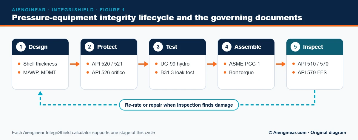
Integrity is not a single calculation. A vessel or piping system is designed, protected, tested, assembled and then inspected for the rest of its life, and each stage has its own governing document. When inspection finds corrosion or damage, the cycle loops back: the equipment is re-rated, repaired or assessed for fitness for service.
2. All 9 IntegriShield calculators
Each tool names its method, runs in the browser and prints a branded record for your calculation file.
Aienginear IntegriShield · Table 1
IntegriShield pressure integrity and site safety calculators
9 free tools · grouped by lifecycle stage
| Stage | Calculator | Typical inputs | Key outputs | Method / standard |
|---|---|---|---|---|
| Design | ASME VIII Pressure Vessel Calculator (VesselCalc Pro) | P, T, D, material, joint efficiency, CA | Shell and head thickness, MAWP, MDMT screening, report | ASME VIII Div. 1 and 2, EN 13445-3, PD 5500 |
| Design / inspect | Mechanical Integrity & Pressure Vessel Calculator (ASME Guard) | Geometry, measured thickness, material, service | Integrity and compliance checks for vessels and pressure parts | ASME VIII methods, API 510 inspection concepts |
| Protect | PSV Relief Load Calculator | Scenario, fluid, relieving rate, set pressure, back pressure | Relief load, required area, API 526 orifice letter | API 520 Part I, API 521, API 526 |
| Protect | Tube Rupture Relief Valve Suite | Shell and tube design pressures, tube ID, fluids | 10/13 rule screen, rupture flow, PSV area | API 521 tube-rupture case, API 520, API 526 |
| Protect | Vessel Volume & Calibration Calculator | Diameter, length, head type, liquid level | Partial volume, strapping table, wetted area for fire case | Exact head geometry; API 521 wetted area |
| Test | Hydrotest & Pressure Test Calculator | Design pressure, material, test temperature, volume | Test pressure, fill water, pump, duration, pneumatic stored energy | ASME B31.3, ASME B31.1 |
| Assemble | Bolt Torque & Flange Joint Integrity Calculator | Flange class and size, gasket, bolt grade, nut factor | Target preload, torque, Wm1/Wm2 check, pass sequence | ASME B16.5/B16.47, VIII App. 2, ASME PCC-1-2022 |
| Operate | Tank Volume Calculator | Tank shape, dimensions, level | Volume vs level, ullage, capacity table, liquid weight | Exact geometric integration |
| Site | Field Safety & Construction Utility Suite (SafeSite Construct) | Lift, test or structural inputs | Exclusion zones, rigging and crane checks, steel member checks | AISC 360, site safety practice |
Reviewed 17 October 2026. Screening tools — verify against the design report, vendor data and the code edition in your contract.
3. Quick thickness and test-pressure checker
Run a first check on a cylindrical vessel under internal pressure, or find the minimum test pressure for a vessel or piping system. The thickness tab uses the ASME VIII Division 1 thin-shell equations with dimensions taken in the corroded condition. For nozzles, external pressure, supports and full reports, open the ASME VIII Pressure Vessel Calculator.
Aienginear IntegriShield · Free tool
Quick thickness and test-pressure checker
ASME VIII Div. 1 internal pressure · ASME B31.3 / B31.1 tests · consistent units
Enable JavaScript to use the checker, or follow the worked example below by hand.
Screening aid only. S and E must come from the code edition in your contract (ASME II-D for S). Defaults reproduce the worked example below.
4. Vessel thickness formulas (ASME VIII Division 1)
For internal pressure, Division 1 sizes each component from a simple membrane-stress equation using the allowable stress S from ASME Section II Part D and the weld joint efficiency E. Dimensions are taken in the corroded condition, and the corrosion allowance is added to the result. The thin-shell equations apply while the thickness stays below half the inside radius and P does not exceed 0.385SE.
Aienginear IntegriShield · Table 2
Required thickness and MAWP equations, internal pressure
ASME VIII Div. 1 thin-shell rules · corroded dimensions
| Component | Required thickness | MAWP for given t | Notes |
|---|---|---|---|
| Cylindrical shell — circumferential stress (governs) | t = PR / (SE − 0.6P) | P = SEt / (R + 0.6t) | R = inside radius |
| Cylindrical shell — longitudinal stress | t = PR / (2SE + 0.4P) | P = 2SEt / (R − 0.4t) | Rarely governs |
| Sphere and hemispherical head | t = PR / (2SE − 0.2P) | P = 2SEt / (R + 0.2t) | About half the shell thickness |
| 2:1 ellipsoidal head | t = PD / (2SE − 0.2P) | P = 2SEt / (D + 0.2t) | D = inside diameter |
| Torispherical head (crown L, knuckle 6 % L) | t = 0.885PL / (SE − 0.1P) | P = SEt / (0.885L + 0.1t) | Typical ASME F&D proportions |
| Conical section (half-apex α ≤ 30°) | t = PD / [2cos α (SE − 0.6P)] | P = 2SEt cos α / (D + 1.2t cos α) | Check cone-to-cylinder junction |
Reviewed 17 October 2026. Summary of published rules — the code edition named in your contract governs.
Worked example: 1.5 m vessel at 1.5 MPa
P = 1.5 MPa, inside diameter 1,500 mm, CA = 3 mm  →  corroded R = 753 mm
S = 138 MPa (example value for a carbon-steel plate; take S from ASME II-D), E = 1.0

Shell:   t = 1.5 × 753 / (138 × 1.0 − 0.6 × 1.5) = 1,129.5 / 137.1 = 8.24 mm
         t + CA = 11.24 mm  →  select 12 mm plate (check under-tolerance)
2:1 head: t = 1.5 × 1,506 / (2 × 138 − 0.2 × 1.5) = 8.19 mm  →  + CA = 11.19 mm

MAWP of 12 mm shell (corroded t = 9 mm):
         P = 138 × 1.0 × 9 / (753 + 0.6 × 9) = 1.638 MPa
Hydrotest (UG-99, stress ratio 1.0): 1.3 × 1.638 = 2.13 MPa
Validity check: 0.385SE = 53 MPa, far above 1.5 MPa, and 8.2 mm is well below R/2, so the thin-shell equation applies. The quick checker above reproduces these figures.
5. Relief valve limits and API 526 orifices
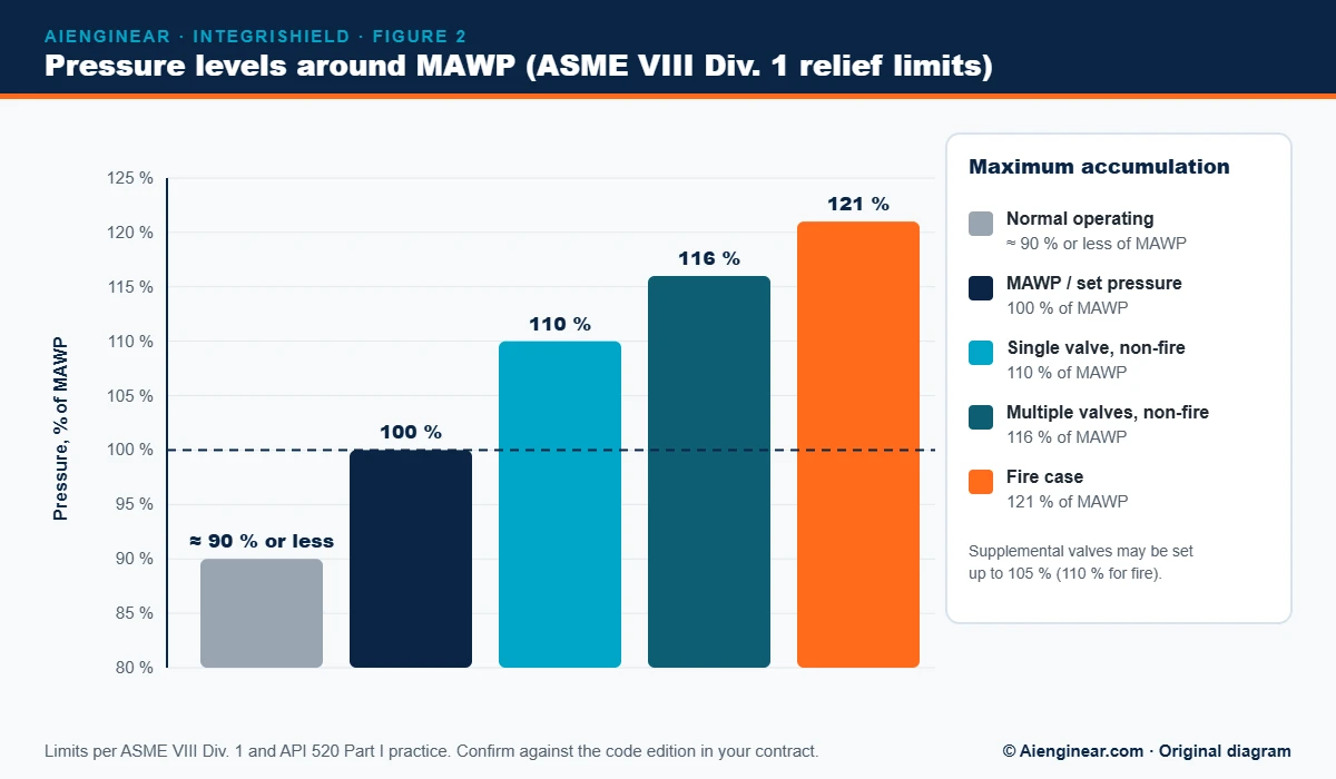
Every vessel needs overpressure protection. The relief device is normally set at or below MAWP, and the pressure is allowed to rise above MAWP only by the accumulation the code permits while the valve discharges. Figure 2 shows the limits that apply to ASME Section VIII Division 1 vessels.
Aienginear IntegriShield · Table 3
Set pressure and allowable accumulation
ASME VIII Div. 1 vessels, sized per API 520 Part I
| Case | Set pressure | Maximum accumulated pressure |
|---|---|---|
| Single relief device, non-fire | ≤ 100 % MAWP | 110 % (or MAWP + 3 psi / 20 kPa, if greater) |
| Multiple devices, non-fire | First ≤ 100 %; others ≤ 105 % | 116 % (or MAWP + 4 psi / 30 kPa, if greater) |
| Fire exposure | ≤ 100 %; supplemental ≤ 110 % | 121 % |
Reviewed 17 October 2026. Summary of published rules — the code edition named in your contract governs.
Relief scenarios — blocked outlet, fire, tube rupture, control-valve failure, thermal expansion and utility loss — come from API 521. Once the governing load is known, API 520 Part I gives the required effective area, and API 526 standardises the orifice letters below.
Aienginear IntegriShield · Table 4
API 526 effective orifice areas
Standard letter designations D to T
| Orifice letter | Effective area, in² | Effective area, mm² |
|---|---|---|
| D | 0.110 | 71 |
| E | 0.196 | 126 |
| F | 0.307 | 198 |
| G | 0.503 | 325 |
| H | 0.785 | 506 |
| J | 1.287 | 830 |
| K | 1.838 | 1,186 |
| L | 2.853 | 1,841 |
| M | 3.60 | 2,323 |
| N | 4.34 | 2,800 |
| P | 6.38 | 4,116 |
| Q | 11.05 | 7,129 |
| R | 16.0 | 10,323 |
| T | 26.0 | 16,774 |
Reviewed 17 October 2026. Effective areas are for sizing to API 520; the actual area and coefficient come from the valve manufacturer’s certified data.
Use the PSV Relief Load Calculator to find the load and pick the letter, the Tube Rupture Relief Valve Suite for exchanger tube failure, and the Vessel Volume Calculator for the wetted area in a fire case.
6. Pressure test rules
A pressure test proves strength and tightness before the system enters service. The test pressure is raised above design to account for the difference between the allowable stress at test temperature and at design temperature.
Aienginear IntegriShield · Table 5
Minimum test pressure by code
Vessels and piping
| Code and test | Minimum test pressure | Key conditions |
|---|---|---|
| ASME VIII Div. 1 — hydrostatic | 1.3 × MAWP × LSR | LSR = lowest ratio of S at test T to S at design T |
| ASME VIII Div. 1 — pneumatic | 1.1 × MAWP × LSR | Only when hydrotest is impracticable; strict precautions |
| ASME VIII Div. 2 — hydrostatic | Greater of 1.43 × MAWP and 1.25 × MAWP × (ST/S) | Check general primary membrane stress during test |
| ASME B31.3 — hydrostatic leak test | 1.5 × P × RR | RR = ST/S, not more than 6.5; keep below yield |
| ASME B31.3 — pneumatic leak test | 1.1 × P | Preliminary 170 kPa check; written procedure |
| ASME B31.1 — hydrostatic | ≥ 1.5 × design pressure | Hold for inspection of all joints |
Reviewed 17 October 2026. Summary of published rules — the code edition named in your contract governs.
Pneumatic tests are hazardous. Compressed gas stores far more energy than water at the same pressure. Use an approved procedure, a stored-energy calculation and an exclusion zone, as covered by ASME PCC-2 guidance and your site rules. The Hydrotest & Pressure Test Calculator and the Field Safety Suite include stored-energy and exclusion screening.
7. Flange joint assembly
Most leaks at start-up come from flanged joints, not from vessel walls. ASME PCC-1-2022 sets out a controlled assembly process: correct gasket and bolting, a target bolt stress, and a tightening pattern applied in several passes. The Bolt Torque & Flange Calculator turns the target preload into a torque for your nut factor, checks it against the ASME VIII Appendix 2 gasket loads, and lays out the passes.
- Pick a target bolt stress that seats the gasket without crushing it or yielding the bolts.
- Use a known nut factor — lubricant choice can change the torque needed by 30 % or more.
- Tighten in passes with a cross pattern or a multi-bolt method, then a final check pass.
- Record the joint: gasket, bolt grade, torque, sequence and the technician, for traceability.
8. Site safety checks
Aienginear IntegriShield · Table 6
Site safety checks supported by IntegriShield
Construction, shutdown and commissioning
| Hazard | What to calculate | Reference | Aienginear tool |
|---|---|---|---|
| Pressure test exclusion | Stored energy of test medium; distance to people | ASME PCC-2 guidance; site permit | Field Safety Suite |
| Lifting and rigging | Load, radius, crane chart capacity, sling angles | ASME B30 series; local regulations | Field Safety Suite |
| Temporary steel and supports | Member stresses under construction loads | AISC 360-22 | Field Safety Suite |
| Vessel entry | Volume for purging and ventilation, gas testing | Confined-space rules (e.g. OSHA 1910.146) | Vessel Volume |
| Inventory during maintenance | Liquid hold-up at a given level | Site isolation procedure | Tank Volume |
Reviewed 17 October 2026. Site rules, permits and local regulations always take precedence.
9. Standards behind IntegriShield
Aienginear IntegriShield · Table 7
Codes and references used in IntegriShield
Edition status checked 17 October 2026
| Standard | Edition position | Scope |
|---|---|---|
| ASME BPVC Section VIII, Div. 1 and 2 | 2025 edition | Pressure vessel design, fabrication, testing, overpressure protection |
| ASME BPVC Section II, Part D | 2025 edition | Allowable stresses S |
| API Std 520 Part I / API Std 521 | Current API editions | Relief sizing; relief scenarios and disposal systems |
| API Std 526 | Current API edition | Flanged steel PSV dimensions and orifice letters |
| ASME B31.3 / B31.1 | 2024 editions | Process and power piping, leak and hydro tests |
| ASME PCC-1 | 2022 edition | Bolted flange joint assembly |
| ASME PCC-2 | Edition per contract | Repair of pressure equipment; pressure-test safety guidance |
| API 510 | 11th edition (2022) | In-service inspection, repair and re-rating of vessels |
| API 579-1 / ASME FFS-1 | 2021 edition | Fitness-for-service assessment |
| ASME B16.5 | 2025 edition | Flange pressure-temperature ratings |
| AISC 360 | 2022 edition | Structural steel design |
Reviewed 17 October 2026. Aienginear paraphrases published rules and does not reproduce copyrighted tables. The edition named in your contract governs.
10. Common integrity mistakes
- Using new instead of corroded dimensions in the thickness equation — always add CA to the radius and to the result.
- Taking S at the wrong temperature or from an old edition of Section II Part D.
- Forgetting mill under-tolerance on pipe (typically 12.5 %) and forming thinning on heads.
- Setting the relief valve above MAWP without the multiple-valve or fire-case justification.
- Choosing a pneumatic test for convenience rather than necessity.
- Torquing flanges without a known nut factor or tightening in a single pass.
- Ignoring the test stress — a high stress ratio can push parts close to yield during hydrotest.
11. Related hubs and guides
- All 33 Aienginear engineering calculators — the full directory
- FlowStack — Process & Hydraulics hub — line sizing, pressure drop, pumps and NPSH
- MechCore — Mechanical, Energy & Documentation hub — insulation, metal weights, DocuEngine
- Two-Phase Separator Sizing Calculator and Heat Exchanger Sizing Calculator — the vessels you protect here
- ASTM A105 forgings and ASTM A53 pipe — common pressure-part materials
- Pipe fittings inspection guide and pipe inspection — receiving and in-service checks
- Plant turnaround and shutdown — where tests, torque and inspection come together
12. Frequently asked questions
What is IntegriShield?
IntegriShield is Aienginear’s pressure integrity and site safety hub: nine free calculators for ASME VIII vessel thickness and MAWP, relief valve sizing to API 520, 521 and 526, pressure tests to ASME B31.3 and B31.1, flange bolt torque to ASME PCC-1, vessel and tank volumes, and field safety checks.
How do you calculate the required thickness of a pressure vessel shell?
Under ASME VIII Division 1, the required thickness of a cylindrical shell for internal pressure is t = PR/(SE − 0.6P), using the corroded inside radius R, the allowable stress S and the joint efficiency E. The corrosion allowance is then added. The formula applies while P does not exceed 0.385SE.
What is the hydrostatic test pressure for an ASME VIII vessel?
For Division 1 vessels the minimum hydrostatic test pressure is 1.3 times MAWP multiplied by the lowest ratio of the allowable stress at test temperature to that at design temperature. A pneumatic test uses 1.1 times MAWP times the same ratio.
What is the hydrotest pressure for ASME B31.3 piping?
ASME B31.3 requires a hydrostatic leak test of at least 1.5 times the design pressure multiplied by the stress ratio ST/S, with the ratio capped at 6.5, while keeping the test stress below yield.
How much can pressure rise above MAWP when a relief valve opens?
For ASME VIII Division 1 vessels, accumulation is limited to 10 % above MAWP with a single relief device, 16 % with multiple devices and 21 % for fire exposure.
What are the API 526 orifice sizes?
API 526 uses letters D through T. Effective areas range from 0.110 in² (71 mm²) for D to 26.0 in² (16,774 mm²) for T, with E, F, G, H, J, K, L, M, N, P, Q and R in between.
Which edition of ASME PCC-1 is current?
ASME PCC-1-2022, Guidelines for Pressure Boundary Bolted Flange Joint Assembly, is the current edition on the review date of this page.
Are IntegriShield results suitable for final design?
They are screening-grade checks. Final vessel design, relief studies and test procedures must be prepared and approved by qualified engineers against the code edition named in the contract.

Written by Muhammad Raza
Founder of Aienginear. Engineering and digital solutions professional with 26+ years managing projects, plant shutdowns and turnarounds in oil & gas, petrochemical and power generation.