
Quick answer
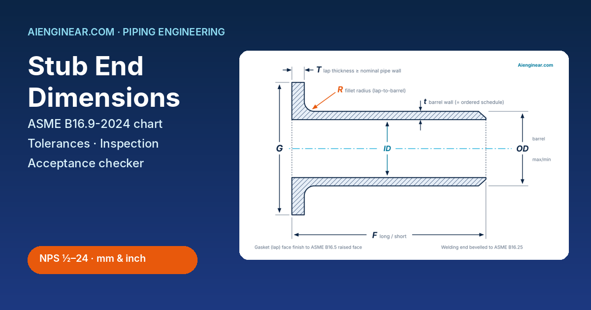
A stub end (lap-joint stub end) is a short butt-welding fitting with a lap that seats a loose lap-joint flange. Stub end dimensions for NPS ½ to 24 are set by ASME B16.9-2024: lap diameter G 35–692 mm, overall length F 76–305 mm in long pattern or 51–152 mm in short pattern, fillet radius R 3–13 mm and barrel OD max/min limits. Lap thickness T must be at least the nominal pipe wall, and the purchase order must state long or short pattern.
Key takeaways
- Governing standard: ASME B16.9-2024 (published 16 October 2024) for factory-made wrought stub ends; MSS SP-43 for light-wall, low-pressure corrosion-resistant stub ends.
- Pattern is not optional: long and short patterns share G, R and barrel OD limits but differ in F – write the pattern on the purchase order.
- Length tolerance is ±2 mm (±0.06 in to NPS 8, ±0.09 in for NPS 10–24) – not the ±3/±6 mm cap tolerance that many charts wrongly apply.
- One-sided tolerances: G and R may only be smaller than nominal (+0); T may only be thicker (−0).
- Fastest check: the Stub End Selector & Acceptance Checker below gives every limit for a size and tests your readings in seconds.
1. What is a lap-joint stub end?
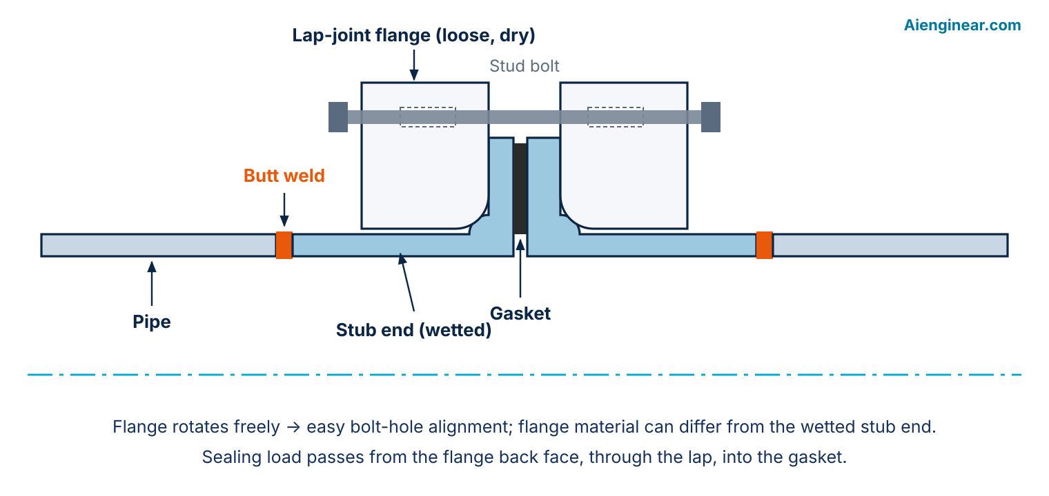
A lap-joint stub end is a short wrought butt-welding fitting. One end is a plain barrel, bevelled and butt-welded to the pipe; the other end is a formed or machined lap whose front face becomes the gasket seating surface. A loose lap-joint (backing) flange slides over the barrel and clamps the lap against the mating joint when the bolts are tightened.
Because the flange never touches the process fluid, it can be ordinary carbon steel even when the pipe and stub end are stainless, duplex or nickel alloy – a real saving on large alloy systems. The flange also rotates freely, so bolt holes line up with equipment nozzles without forcing the pipe. Stub ends belong to the same ASME B16.9 family as elbows, tees, reducers and return bends; see our overview of types of pipe fittings for where they fit in a piping system.
When to use a stub end – and when not to
- Good fit: stainless, duplex or nickel-alloy lines; systems dismantled often for cleaning or inspection; tie-ins where bolt-hole orientation is uncertain.
- Use with care: lines with high bending loads, vibration or thermal cycling – a lap joint has lower fatigue strength than a weld neck flange.
- Avoid without engineering review: severe cyclic service and high-class joints where the piping code or project specification calls for weld neck flanges.
2. Stub end nomenclature: G, F, T, R, OD and t
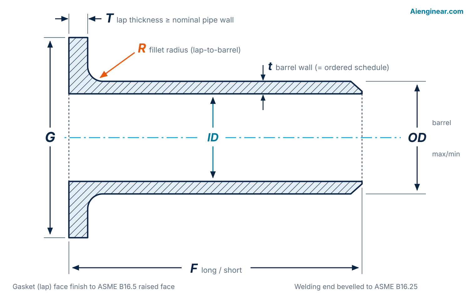
ASME B16.9 uses a small set of letters for stub ends. Using the same letters on drawings, inspection reports and purchase orders removes most dimensional disputes with suppliers.
| Symbol | Dimension | What it means in practice |
|---|---|---|
| NPS / DN | Nominal size | A size designation only. NPS 2 pipe is 60.3 mm OD, not 2 in – never measure NPS. |
| OD | Barrel outside diameter | Checked against the max/min limits in Table 2; it must suit the mating pipe OD. |
| G | Lap (stub) outside diameter | Gasket-seating diameter. Equal to the raised-face diameter of an ASME B16.5 flange of the same size. Tolerance +0. |
| F | Overall length | Lap face to welding end. Long or short pattern – the purchaser must specify which. |
| T | Lap thickness | Not less than the nominal pipe wall. Extra thickness for tongue/groove or male/female facings is added and is not included in F. |
| R | Fillet radius | Lap-to-barrel transition. Must clear the bore corner of the lap-joint flange so the flange seats fully. Tolerance +0. |
| t | Barrel wall thickness | Ordered schedule or wall (Sch 10S, 40S/STD, 80S/XS…). Minimum 87.5 % of nominal unless the PO states otherwise. |
| ID | Inside diameter at end | Specified by the purchaser; by default nominal OD minus twice the nominal wall. |
Aienginear.com · Piping Engineering Reference · ASME B16.9-2024
3. ASME B16.9 stub end dimensions chart (NPS ½–24)
The chart lists every lap-joint stub end size in ASME B16.9-2024. Switch between millimetres and inches, type a size to highlight its row, or download the full chart as CSV. The pipe OD column (from ASME B36.10M / B36.19M, see our pipe sizes and schedule chart) is included so you can see how the barrel limits bracket the mating pipe.
| NPS | DN | Pipe OD ref. | Barrel OD max | Barrel OD min | Lap dia. G | F long | F short | Fillet R |
|---|---|---|---|---|---|---|---|---|
| ½ | 15 | 21.3 | 22.8 | 20.5 | 35 | 76 | 51 | 3 |
| ¾ | 20 | 26.7 | 28.1 | 25.9 | 43 | 76 | 51 | 3 |
| 1 | 25 | 33.4 | 35.0 | 32.6 | 51 | 102 | 51 | 3 |
| 1¼ | 32 | 42.2 | 43.6 | 41.4 | 64 | 102 | 51 | 5 |
| 1½ | 40 | 48.3 | 49.9 | 47.5 | 73 | 102 | 51 | 6 |
| 2 | 50 | 60.3 | 62.4 | 59.5 | 92 | 152 | 64 | 8 |
| 2½ | 65 | 73.0 | 75.3 | 72.2 | 105 | 152 | 64 | 8 |
| 3 | 80 | 88.9 | 91.3 | 88.1 | 127 | 152 | 64 | 10 |
| 3½ | 90 | 101.6 | 104.0 | 100.8 | 140 | 152 | 76 | 10 |
| 4 | 100 | 114.3 | 116.7 | 113.5 | 157 | 152 | 76 | 11 |
| 5 | 125 | 141.3 | 144.3 | 140.5 | 186 | 203 | 76 | 11 |
| 6 | 150 | 168.3 | 171.3 | 167.5 | 216 | 203 | 89 | 13 |
| 8 | 200 | 219.1 | 222.1 | 218.3 | 270 | 203 | 102 | 13 |
| 10 | 250 | 273.1 | 277.2 | 272.3 | 324 | 254 | 127 | 13 |
| 12 | 300 | 323.8 | 328.0 | 323.1 | 381 | 254 | 152 | 13 |
| 14 | 350 | 355.6 | 359.9 | 354.8 | 413 | 305 | 152 | 13 |
| 16 | 400 | 406.4 | 411.0 | 405.6 | 470 | 305 | 152 | 13 |
| 18 | 450 | 457.2 | 462.0 | 456.0 | 533 | 305 | 152 | 13 |
| 20 | 500 | 508.0 | 514.0 | 507.0 | 584 | 305 | 152 | 13 |
| 22 | 550 | 558.8 | 565.0 | 558.0 | 641 | 305 | 152 | 13 |
| 24 | 600 | 609.6 | 616.0 | 609.0 | 692 | 305 | 152 | 13 |
Basis: ASME B16.9-2024 lap-joint stub end table. Pipe OD reference from ASME B36.10M / B36.19M. Compiled by Aienginear.com – verify against your licensed copy.
| NPS | DN | Pipe OD ref. | Barrel OD max | Barrel OD min | Lap dia. G | F long | F short | Fillet R |
|---|---|---|---|---|---|---|---|---|
| ½ | 15 | 0.840 | 0.896 | 0.809 | 1.38 | 3.00 | 2.00 | 0.12 |
| ¾ | 20 | 1.050 | 1.106 | 1.019 | 1.69 | 3.00 | 2.00 | 0.12 |
| 1 | 25 | 1.315 | 1.376 | 1.284 | 2.00 | 4.00 | 2.00 | 0.12 |
| 1¼ | 32 | 1.660 | 1.716 | 1.629 | 2.50 | 4.00 | 2.00 | 0.19 |
| 1½ | 40 | 1.900 | 1.966 | 1.869 | 2.88 | 4.00 | 2.00 | 0.25 |
| 2 | 50 | 2.375 | 2.456 | 2.344 | 3.62 | 6.00 | 2.50 | 0.31 |
| 2½ | 65 | 2.875 | 2.966 | 2.844 | 4.12 | 6.00 | 2.50 | 0.31 |
| 3 | 80 | 3.500 | 3.596 | 3.469 | 5.00 | 6.00 | 2.50 | 0.38 |
| 3½ | 90 | 4.000 | 4.096 | 3.969 | 5.50 | 6.00 | 3.00 | 0.38 |
| 4 | 100 | 4.500 | 4.593 | 4.469 | 6.19 | 6.00 | 3.00 | 0.44 |
| 5 | 125 | 5.563 | 5.683 | 5.532 | 7.31 | 8.00 | 3.00 | 0.44 |
| 6 | 150 | 6.625 | 6.743 | 6.594 | 8.50 | 8.00 | 3.50 | 0.50 |
| 8 | 200 | 8.625 | 8.743 | 8.594 | 10.62 | 8.00 | 4.00 | 0.50 |
| 10 | 250 | 10.750 | 10.913 | 10.719 | 12.75 | 10.00 | 5.00 | 0.50 |
| 12 | 300 | 12.750 | 12.913 | 12.719 | 15.00 | 10.00 | 6.00 | 0.50 |
| 14 | 350 | 14.000 | 14.170 | 13.969 | 16.25 | 12.00 | 6.00 | 0.50 |
| 16 | 400 | 16.000 | 16.180 | 15.969 | 18.50 | 12.00 | 6.00 | 0.50 |
| 18 | 450 | 18.000 | 18.190 | 17.969 | 21.00 | 12.00 | 6.00 | 0.50 |
| 20 | 500 | 20.000 | 20.240 | 19.969 | 23.00 | 12.00 | 6.00 | 0.50 |
| 22 | 550 | 22.000 | 22.240 | 21.969 | 25.25 | 12.00 | 6.00 | 0.50 |
| 24 | 600 | 24.000 | 24.240 | 23.969 | 27.25 | 12.00 | 6.00 | 0.50 |
Basis: ASME B16.9-2024 lap-joint stub end table. Pipe OD reference from ASME B36.10M / B36.19M. Compiled by Aienginear.com – verify against your licensed copy.
4. Long pattern vs short pattern stub ends
Both patterns share the same lap diameter, fillet radius and barrel OD limits – only the overall length F changes. The choice is driven by flange thickness, weld access and cost.
| Feature | Long pattern | Short pattern |
|---|---|---|
| Overall length F | 76–305 mm (3–12 in) | 51–152 mm (2–6 in) |
| G, R and barrel OD | Identical to short pattern | Identical to long pattern |
| Weld clearance behind the flange | Generous – the weld normally stays clear of the flange | Limited – check flange thickness and class |
| Typical use | Class 300 and above, larger NPS, thick flanges, field fit-up | Class 150 compact runs, skids, light-wall stainless (MSS SP-43) |
| Weight and cost | Higher | Lower |
Aienginear.com · Piping Engineering Reference · ASME B16.9-2024
5. Stub end types, standards and materials
| Type | Construction | Scope / service | Engineering note |
|---|---|---|---|
| ASME B16.9 stub end | Wrought, factory-made; formed, forged or machined lap | NPS ½–24, long or short pattern | Standard choice for ASME B31.3 / B31.1 process and power piping |
| MSS SP-43 Type A | Lap and fillet made to suit standard lap-joint flanges | Light wall (typically Sch 5S/10S), low-pressure, corrosion-resistant service | Dimensions and tolerances largely follow B16.9 for NPS ½–24, except the OD at the bevel |
| MSS SP-43 Type B | Near-square lap corner (small maximum R) | For use with slip-on flanges as backing flanges | Check the backing-flange bore and corner against the barrel and R |
| Fabricated or flared lap (ASME B31.3) | Lap ring welded to pipe, or flared pipe end | Only where the governing code and project specification allow | Lap OD must meet B16.9 stub-end limits; fillet radius and minimum lap thickness are limited by the code |
Aienginear.com · Piping Engineering Reference · ASME B16.9-2024
MSS SP-43 stub ends are intended for light-wall stainless systems in low-pressure, corrosion-resistant service; they are not a substitute for B16.9 fittings in pressure-designed lines unless the design basis allows it. Fabricated laps (a ring welded to the pipe) are a code construction, not a catalogue item – confirm the governing code and project specification permit them before use.
Common stub end materials
| Material family | Typical fitting specification | Typical service |
|---|---|---|
| Carbon steel | ASTM A234/A234M WPB | General hydrocarbon, steam, water |
| Low-temperature carbon steel | ASTM A420/A420M WPL6 | Impact-tested service down to about −46 °C |
| Alloy (Cr-Mo) steel | ASTM A234/A234M WP11, WP22, WP91 | High-temperature steam and refinery service |
| Austenitic stainless | ASTM A403/A403M WP304/304L, WP316/316L (class S, W, WX or WU); class CR for MSS SP-43 | Corrosive chemicals, food, pharmaceutical, cryogenic |
| Duplex / super-duplex | ASTM A815/A815M WPS31803, WPS32205, WPS32750 | Chlorides, seawater, offshore |
| Nickel alloys | ASTM B366 WPNCMC (Alloy 625), WPHC276 (Alloy C-276) | Severe acids, high temperature |
Aienginear.com · Piping Engineering Reference · ASME B16.9-2024
The backing flange is usually ASTM A105 carbon steel (ASTM A350 LF2 for low temperature). Check galvanic and temperature compatibility, especially in coastal plants where a carbon-steel flange sits against a stainless lap, and size the bolting with a proper bolt torque and flange joint calculation.
6. Stub end tolerances (ASME B16.9)
The table isolates what applies to a stub end: the general welding-end tolerances plus the stub-end limits on G, R and T. Tolerances are equal plus and minus unless shown otherwise. The unit switch above also changes this table.
| NPS | OD at bevel | ID at end | Overall length F | Lap dia. G | Fillet R | Lap thickness T |
|---|---|---|---|---|---|---|
| ½–2½ | +1.6 / −0.8 | ±0.8 | ±2 | +0 / −1 | +0 / −1 | +1.6 / −0 |
| 3–3½ | ±1.6 | ±1.6 | ±2 | +0 / −1 | +0 / −1 | +1.6 / −0 |
| 4 | ±1.6 | ±1.6 | ±2 | +0 / −1 | +0 / −2 | +1.6 / −0 |
| 5–8 | +2.4 / −1.6 | ±1.6 | ±2 | +0 / −1 | +0 / −2 | +1.6 / −0 |
| 10–18 | +4.0 / −3.2 | ±3.2 | ±2 | +0 / −2 | +0 / −2 | +3.2 / −0 |
| 20–24 | +6.4 / −4.8 | ±4.8 | ±2 | +0 / −2 | +0 / −2 | +3.2 / −0 |
Basis: ASME B16.9-2024 tolerance table (stub-end columns). Tolerances are equal plus and minus unless shown. Compiled by Aienginear.com.
| NPS | OD at bevel | ID at end | Overall length F | Lap dia. G | Fillet R | Lap thickness T |
|---|---|---|---|---|---|---|
| ½–2½ | +0.06 / −0.03 | ±0.03 | ±0.06 | +0 / −0.03 | +0 / −0.03 | +0.06 / −0 |
| 3–3½ | ±0.06 | ±0.06 | ±0.06 | +0 / −0.03 | +0 / −0.03 | +0.06 / −0 |
| 4 | ±0.06 | ±0.06 | ±0.06 | +0 / −0.03 | +0 / −0.06 | +0.06 / −0 |
| 5–8 | +0.09 / −0.06 | ±0.06 | ±0.06 | +0 / −0.03 | +0 / −0.06 | +0.06 / −0 |
| 10–18 | +0.16 / −0.12 | ±0.12 | ±0.09 | +0 / −0.06 | +0 / −0.06 | +0.12 / −0 |
| 20–24 | +0.25 / −0.19 | ±0.19 | ±0.09 | +0 / −0.06 | +0 / −0.06 | +0.12 / −0 |
Basis: ASME B16.9-2024 tolerance table (stub-end columns). Tolerances are equal plus and minus unless shown. Compiled by Aienginear.com.
| NPS | Off-angle Q, mm (in) | Off-plane P, mm (in) |
|---|---|---|
| ½–4 | 1 (0.03) | 2 (0.06) |
| 5–8 | 2 (0.06) | 4 (0.12) |
| 10–12 | 3 (0.09) | 5 (0.19) |
| 14–16 | 3 (0.09) | 6 (0.25) |
| 18–24 | 4 (0.12) | 10 (0.38) |
Q = lap face square to the barrel axis; P = off-plane. Basis: ASME B16.9-2024. Compiled by Aienginear.com.
7. Stub End Selector & Acceptance Checker
Pick a size, pattern and wall basis to get every nominal value and acceptance limit in one place. Enter measured readings for an instant accept/reject per dimension, then print the result as a branded inspection record.
Enable JavaScript to use the checker. Tables 2, 6 and 7 above contain the same data.
Measured values (optional)
Record details (optional, printed on the record)
Limits computed from ASME B16.9-2024 stub-end dimensions and tolerances; pipe wall from ASME B36.10M / B36.19M. An aid to inspection – the licensed standard and the PO govern.
8. Stub end inspection procedure (step by step)
This sequence follows the general receiving checks in our pipe fittings inspection guide, with the stub-end-specific checks added.
- Documents first. Compare the fitting against the PO: NPS, wall/schedule, long or short pattern, material grade and class, standard and edition, end preparation and the heat number on the mill test certificate (EN 10204 3.1 or as specified).
- Marking and traceability. Confirm the manufacturer’s mark, material grade, schedule/wall, size and heat code are legible and match the MTC.
- Visual check. Inspect the gasket face, fillet, barrel and bevel for laps, cracks, laminations, dents, pits and handling damage. The gasket face must carry the B16.5 raised-face finish (typically serrated) with no radial scratches.
- Barrel OD. Measure with a calibrated micrometer or π-tape at two orientations 90° apart and check against the barrel OD max/min limits.
- Lap diameter G. Measure across the lap in at least two orientations. Accept only between G minus tolerance and G – an oversize lap interferes with gasket centring inside the bolts.
- Overall length F. Measure lap face to welding end at four points around the fitting; accept within ±2 mm of the ordered pattern length.
- Lap thickness T. Measure at four locations away from the edge chamfer; every reading must be at least the nominal pipe wall.
- Fillet radius R. Check with a radius gauge or profile template. R must not exceed nominal, otherwise the lap-joint flange will not sit flat on the lap.
- Wall thickness and bore. UT-gauge the barrel; the minimum reading must be at least 87.5 % of nominal. Check ID at the end against OD − 2t ± tolerance.
- Angularity. Check off-angle Q (lap face square to the barrel axis) and off-plane P with a square and feeler gauges or on a surface plate.
- Weld bevel. For walls over 3 mm and up to 22 mm, verify a 37.5° ± 2.5° bevel and 1.6 ± 0.8 mm root face per ASME B16.25 (or the preparation required by the WPS); walls of 3 mm and less may be square-cut or slightly chamfered.
- Flange trial fit. Slide the lap-joint flange on: it must rotate freely, seat fully against the back of the lap and leave the butt weld uncovered.
- Record and disposition. Log nominal values, readings, instruments and calibration IDs, heat number, inspector, date and accept/reject. The checker above prints a ready-made record.
9. How to specify a stub end on a purchase order
A complete description prevents the most common supply errors. Give the data in this order:
Stub end, lap joint, LONG pattern, NPS 4 (DN 100), Sch 40S,
ASTM A403 WP316L-S, ASME B16.9-2024, ends bevelled to ASME B16.25,
gasket face to ASME B16.5 RF finish, MTC to EN 10204 3.1.
For an MSS SP-43 light-wall item, replace the standard with MSS SP-43 Type A, use class CR (for example ASTM A403 CR316L) and state the schedule (Sch 10S). Add the matching backing flange as a separate line item – for example “Flange, lap joint, Class 150, NPS 4, ASTM A105, ASME B16.5-2025”.
10. Common stub end mistakes to avoid
- Reading the OD columns of copied charts the wrong way round – many web tables label 22.8 mm as “min” and 20.5 mm as “max” for NPS ½.
- Applying the cap length tolerance (±3 / ±6 mm) to stub ends. The B16.9 length tolerance for stub ends is ±2 mm.
- Accepting a lap that is larger than nominal G, or a fillet larger than nominal R. Both tolerances are +0 – any oversize is a reject.
- Ordering “stub end, NPS 4” without the pattern, schedule, material class and end preparation.
- Pairing a short-pattern stub end with a thick Class 600 or 900 flange so the flange sits over the butt weld.
- Using a slip-on flange as backing for a Type A stub end (or a lap-joint flange on Type B) without checking bore and corner radius.
- Ignoring the gasket-face finish: the lap is the sealing face, so a scratched or unserrated lap will leak whatever its dimensions.
- Treating MSS SP-43 light-wall stub ends as interchangeable with B16.9 fittings for pressure design.
11. Test your knowledge: stub end dimensions quiz
Fifteen quick questions on ASME B16.9-2024 stub end dimensions, long and short pattern, tolerances, MSS SP-43 types, materials and inspection. Pick an answer to see the explanation straight away; your score updates as you go.
Answered 0 of 15.
12. Frequently asked questions
What standard covers stub end dimensions?
ASME B16.9-2024, Factory-Made Wrought Buttwelding Fittings, gives lap-joint stub end dimensions and tolerances for NPS ½ to 24. Light-wall, low-pressure corrosion-resistant stub ends are covered by MSS SP-43 (Types A and B), and the matching lap-joint flanges are dimensioned in ASME B16.5-2025.
What is the difference between long and short pattern stub ends?
Only the overall length F changes. An NPS 4 stub end is 152 mm long in long pattern and 76 mm in short pattern, while G (157 mm), R (11 mm) and the barrel OD limits are identical. Long pattern leaves more weld clearance behind thick flanges.
What is G on a stub end?
G is the outside diameter of the lap, the face that seats the gasket. It equals the raised-face diameter of an ASME B16.5 flange of the same size and has a plus-zero tolerance, so the lap may be slightly smaller than nominal but never larger.
What is the minimum lap thickness of a stub end?
ASME B16.9 requires lap thickness T to be at least the nominal wall thickness of the connected pipe. Its tolerance is plus-only: +1.6 mm up to NPS 8 and +3.2 mm for NPS 10 to 24.
What is the length tolerance for a stub end?
The overall length F of a lap-joint stub end has a tolerance of ±2 mm under ASME B16.9, shown as ±0.06 in for NPS ½–8 and ±0.09 in for NPS 10–24. The larger ±3/±6 mm values apply to caps, not stub ends.
Can a short pattern stub end be used with any flange class?
Not always. ASME B16.9 notes that short-pattern stub ends used with larger Class 300 and 600 flanges, most Class 900 and higher flanges, and long-pattern stub ends with some larger Class 1500 and 2500 flanges may need extra length, agreed with the manufacturer, so the flange does not cover the weld.
Why use a stub end and lap-joint flange instead of a weld neck flange?
The loose flange rotates for easy bolt-hole alignment and never touches the process fluid, so it can be carbon steel while only the stub end matches an expensive alloy pipe. The trade-off is lower bending and fatigue resistance than a weld neck joint.
What is the difference between a stub end and a lap joint flange?
The stub end is the butt-welded fitting that carries the gasket face and is wetted by the fluid. The lap-joint flange is the loose backing ring that slides over it and carries the bolt load; it is never welded and never wetted.
13. Summary
A stub end is accepted on six numbers – barrel OD, G, F, T, R and wall – plus angularity, bevel and face finish. Take nominal values from ASME B16.9-2024, apply the stub-end tolerances (G and R plus-zero, T minus-zero, F ±2 mm), confirm the pattern and the weld clearance behind the flange, and record every reading. The selector above does the arithmetic and prints the record for you. Ready to test yourself? Try the stub end dimensions quiz above.
Related Aienginear guides and tools
References
- ASME B16.9-2024, Factory-Made Wrought Buttwelding Fittings (published 16 October 2024) – stub end dimensions, tolerances and notes.
- ASME B16.5-2025, Pipe Flanges and Flanged Fittings: NPS ½ through NPS 24 – lap-joint flange dimensions, raised-face diameters and facing finish.
- ASME B16.25-2022, Buttwelding Ends – weld bevel and root face geometry.
- MSS SP-43, Wrought and Fabricated Butt-Welding Fittings for Low Pressure, Corrosion Resistant Applications – Type A and Type B stub ends.
- ASME B31.3-2024, Process Piping – fabricated and flared laps and flanged joints.
- ASME B36.10M and ASME B36.19M – welded/seamless and stainless steel pipe dimensions and schedules.
- ASTM A234/A234M, A403/A403M, A420/A420M, A815/A815M and B366 – wrought fitting material specifications.

Written by Muhammad Raza
Founder of Aienginear. Mechanical engineer (BSc, UET Lahore) and Head of Projects with 18+ years managing piping, mechanical installation, plant shutdowns and turnarounds in power, cement, fertilizer and oil & gas plants.