
AIENGINEAR CALCULATOR · VESSELS & TANKS
Quick answer: how do you calculate vessel volume?
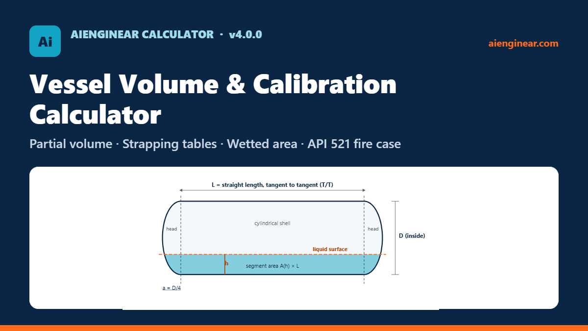
Treat the vessel as a cylindrical shell plus two heads. The shell holds (π/4)·D²·L, where D is the inside diameter and L is the tangent-to-tangent length. Add the head volumes: 0.1309·D³ for each 2:1 semi-ellipsoidal head, 0.2618·D³ for each hemispherical head and about 0.0810·D³ for each ASME flanged-and-dished head. For a part-full horizontal vessel, the shell holds the circular-segment area at the liquid height multiplied by L, so volume does not rise in step with level.
The free Aienginear calculator below does this for horizontal, vertical, inclined and spherical vessels, and builds the full level-to-volume (strapping) table.
Key takeaways
- Always work with inside dimensions. Outside diameter less two wall thicknesses gives the inside diameter.
- In a horizontal drum, the bottom 25% of the level holds only about 19.6% of the volume. Alarm and trip levels must be set from a strapping table, not by proportion.
- Two 2:1 heads together hold the same volume as a length of shell equal to D/3. This is a quick sense check on any result.
- Wetted area for an API 521 fire case is counted only up to the lower of the liquid level and the fire-zone height, commonly 7.6 m (25 ft) above grade.
- A tilt of only 1° to 2° shifts the low-level readings of a long horizontal drum. Version 4 models the inclined vessel directly.
How to use the calculator
The tool answers two questions. Given a liquid level, how much is in the vessel? And given a volume, a fill percentage or a mass, what level should the gauge show? Work down the six input panels in order.
- Choose the orientation. Horizontal, vertical or sphere. Horizontal vessels can also be given a tilt and a gauge position.
- Enter the diameter and length. Use the inside diameter, or switch the basis to outside diameter and wall thickness. The length is tangent to tangent, so it includes the straight flanges of the heads.
- Pick the heads. Eleven head types are available, including ASME F&D, DIN 28011 Klöpper, DIN 28013 Korbbogen, 80:10, conical and toriconical. Untick “same as first” to give each end a different head, for example a cone bottom and a 2:1 top.
- Set the liquid level and density. Type the level or drag the slider. The density turns volume into mass.
- Enter level settings and flow. LLLL to HHLL as a percentage of height, plus the draw-off nozzle. The tool gives the volume between each pair and the time it lasts at your flow rate.
- Read, export or print. Results, sketch, calibration curve and strapping table update as you type. Export to CSV, Excel, JSON or SVG, or print a branded PDF report.
Practical tip. Before trusting any vessel spreadsheet, enter a 2:1 drum with D = 2 m and L = 6 m. The total should be 20.94 m³. The calculator’s self-check line also compares every result with an independent solution and shows the difference.
What is new in version 4.0.0 (October 2026)
- A rebuilt geometry engine that integrates the true head profile, giving the same method and accuracy for every head type.
- Inclined horizontal vessels, with the level read at any gauge station along the shell.
- Different heads at each end, and dished-in (concave) heads that are deducted from the shell.
- Klöpper (DIN 28011), Korbbogen (DIN 28013), custom torispherical, custom ellipsoidal and toriconical heads.
- A level-setting table with hold-up, surge and residence times, dead volume and working volume.
- API 521 fire case: fire-exposed wetted area and heat input with and without adequate drainage.
- Reverse solver by volume, by fill percentage or by mass.
- Strapping tables in percentage steps or fixed length steps (up to 5,000 rows), with CSV, Excel, JSON, SVG and print export.
Vessel geometry and head types
Every process vessel in the calculator is built from three parts: a cylindrical shell between the two tangent lines, and a head at each end. The tangent line is where the straight part of a formed head meets its curved part. Head depth is measured from that line to the inside of the crown.
Head shape changes both the depth and the volume. A flat end adds nothing. A hemisphere adds the most. The torispherical family, which most fabricators roll from plate, sits between a 2:1 head and a flat end. Figure 2 draws the common types at the same diameter.
Aienginear Table 1
Head depth, volume and surface coefficients
Multiply by the inside diameter D (depth), D³ (volume) or D² (inside surface)
| Head type | Geometry (crown R, knuckle r) | Depth / D | Volume / D³ | Inside surface / D² | Typical code reference |
|---|---|---|---|---|---|
| Flat | Plate or blind flange | 0 | 0 | 0.7854 | ASME VIII-1 UG-34 |
| ASME F&D torispherical | R = D, r = 0.06D | 0.1693 | 0.0810 | 0.9306 | ASME VIII-1 UG-32 |
| Klöpper | R = D, r = 0.10D | 0.1938 | 0.0990 | 0.9900 | DIN 28011 |
| 80:10 torispherical | R = 0.8D, r = 0.10D | 0.2255 | 0.1099 | 1.0147 | Fabricator standard |
| Korbbogen | R = 0.8D, r = 0.154D | 0.2545 | 0.1308 | 1.0879 | DIN 28013 |
| 2:1 semi-ellipsoidal | Depth = D/4 | 0.2500 | 0.1309 | 1.0840 | ASME VIII-1 UG-32 |
| Hemispherical | Depth = D/2 | 0.5000 | 0.2618 | 1.5708 | ASME VIII-1 UG-32 |
| Conical, α = 30° | Half-angle from the axis | 0.8660 | 0.2267 | 1.5708 | ASME VIII-1 UG-32, UG-33 |
| Conical, α = 45° | Half-angle from the axis | 0.5000 | 0.1309 | 1.1107 | ASME VIII-1 (above 30° needs extra analysis) |
| Toriconical, α = 30° | Knuckle r = 0.10D | 0.8928 | 0.2476 | 1.6508 | ASME VIII-1 UG-32 |
Two points from Table 1 are worth remembering. The 2:1 head and the Korbbogen head hold almost the same volume. The ASME F&D head, which is the shallowest common dished head, holds about 38% less than a 2:1 head of the same diameter. Picking the wrong head type in a calculator is one of the most common sources of error in vessel inventories.
Full volume formulas
With R = D/2 as the inside radius and a as the head depth, the full volume of each part is:
Ellipsoidal or hemispherical head: Vh = (2/3)·π·R²·a (2:1 head: π·D³/24; hemisphere: π·D³/12)
Conical head: Vh = (1/3)·π·R²·a, with a = R / tan α
Torispherical head: crown cap of radius Rc plus a toroidal knuckle of radius r, solved from the profile
Total: V = Vs + Vh1 + Vh2 (dished-in heads are subtracted)
Torispherical heads have no neat single-term formula, because the crown and the knuckle are two different arcs. The calculator does not use a fitted coefficient for them. It traces the actual meridian, with the knuckle arc running into the crown arc at the point where they share a tangent, and integrates the volume of revolution. The same method serves every head type, and the result for the ellipsoidal, hemispherical and conical heads matches the closed-form values to better than 0.001%.
Partial volume of a horizontal vessel
In a horizontal vessel the liquid cross-section in the shell is a circular segment. At liquid height h above the bottom of the shell, with R the inside radius:
Shell liquid: Vs(h) = A(h)·L
Two equal ellipsoidal heads together: Vh(h) = (a/R)·π·h²·(3R − h)/3
Liquid surface width: w(h) = 2·√(2Rh − h²)
The head expression follows from a neat property: a pair of ellipsoidal heads, placed end to end, forms an ellipsoid. That ellipsoid is a sphere stretched along one axis by the ratio a/R, so its partial volume is the spherical-cap volume scaled by a/R. For torispherical and conical heads, the calculator sums thin slices of the head, each a circular segment of its own radius at the same liquid height.
Aienginear Table 2
Horizontal vessel: percent full against level
Level h as a fraction of inside diameter; vessels with L/D = 3
| h / D | Plain cylinder, % full | With 2:1 heads, % full | With hemispherical heads, % full |
|---|---|---|---|
| 0.00 | 0.00 | 0.00 | 0.00 |
| 0.05 | 1.87 | 1.75 | 1.66 |
| 0.10 | 5.20 | 4.96 | 4.77 |
| 0.15 | 9.41 | 9.07 | 8.80 |
| 0.20 | 14.24 | 13.85 | 13.54 |
| 0.25 | 19.55 | 19.16 | 18.84 |
| 0.30 | 25.23 | 24.87 | 24.57 |
| 0.35 | 31.19 | 30.89 | 30.64 |
| 0.40 | 37.35 | 37.14 | 36.96 |
| 0.45 | 43.64 | 43.53 | 43.44 |
| 0.50 | 50.00 | 50.00 | 50.00 |
| 0.55 | 56.36 | 56.47 | 56.56 |
| 0.60 | 62.65 | 62.86 | 63.04 |
| 0.65 | 68.81 | 69.11 | 69.36 |
| 0.70 | 74.77 | 75.13 | 75.43 |
| 0.75 | 80.45 | 80.84 | 81.16 |
| 0.80 | 85.76 | 86.15 | 86.46 |
| 0.85 | 90.59 | 90.93 | 91.20 |
| 0.90 | 94.80 | 95.04 | 95.23 |
| 0.95 | 98.13 | 98.25 | 98.34 |
| 1.00 | 100.00 | 100.00 | 100.00 |
Table 2 shows why the heads matter less than the shell for level-to-volume shape. The three columns differ by less than one percentage point at any level, because the heads are a small share of a vessel with L/D = 3. For short vessels, or vessels with hemispherical heads, use the calculator rather than the plain-cylinder column.
Partial volume of a vertical vessel
A vertical vessel fills from the bottom head upward. While the liquid is inside the bottom head, the volume follows that head’s own depth-volume curve: a cap for an ellipsoidal or hemispherical head, a small cone for a conical bottom. Once the liquid passes the bottom tangent line, every extra unit of height adds (π/4)·D² of volume, which is why a vertical vessel is the only shape with a straight-line calibration in the shell.
2:1 bottom head, liquid depth y ≤ a: V = (π·R²/a²)·(a·y² − y³/3)
Conical bottom, liquid depth y ≤ a: V = (π/3)·(y·tan α)²·y
Choose the level datum carefully. Instrument engineers often set zero at the bottom tangent line, while operators and dip tapes measure from the lowest point. The calculator offers both; the difference is the bottom head depth, which is 375 mm on a 1.5 m vessel with 2:1 heads.
Inclined (tilted) horizontal vessels
Horizontal drums are often installed with a deliberate slope toward a drain or boot, and old vessels settle on their saddles. A tilted vessel no longer has a single relationship between level and volume. The answer depends on where along the shell the level is read.
Version 4 handles this directly. It slices the vessel into thin discs perpendicular to its axis, works out where the horizontal liquid surface cuts each disc, and adds the slices. The level is measured vertically at the gauge station you choose, from the shell bottom at that station. At a 2° tilt on a 2 m × 6 m drum read at mid-length, the volume at a 200 mm level is about 3.5% higher than the level-vessel value, while the 500 mm reading changes by under 0.3%. Low levels, where pump protection and draining decisions are made, are where tilt matters.
Watch out. On a tilted vessel, a level of zero at the gauge does not mean empty. Liquid can still lie in the low end. The calculator reports negative levels for that region, so the strapping table starts below zero.
Worked example 1: horizontal drum with 2:1 heads
A knock-out drum has an inside diameter of 2.0 m, a tangent-to-tangent length of 6.0 m and two 2:1 semi-ellipsoidal heads (depth a = 0.5 m). Find the total volume and the liquid at a 0.5 m level.
- Shell: (π/4) × 2.0² × 6.0 = 18.850 m³.
- Heads: 2 × π × 2.0³ / 24 = 2.094 m³.
- Total: 20.944 m³, which is about 5,533 US gal or 131.7 bbl.
- Segment area at h = 0.5 m: 1.0² × cos⁻¹(0.5) − 0.5 × √(2 × 1.0 × 0.5 − 0.25) = 1.0472 − 0.4330 = 0.6142 m². Shell liquid = 0.6142 × 6.0 = 3.685 m³.
- Heads at h = 0.5 m: (0.5/1.0) × π × 0.5² × (3.0 − 0.5)/3 = 0.327 m³.
- Liquid: 4.012 m³, so the drum is 19.2% full at 25% of its diameter.
Aienginear Table 3
Worked example 1: strapping table extract
D = 2.0 m, L = 6.0 m, two 2:1 heads, level from shell bottom
| Level (m) | Volume (m³) | Fill % | Wetted area (m²) | Liquid surface (m²) |
|---|---|---|---|---|
| 0.0 | 0.000 | 0.00 | 0.00 | 0.00 |
| 0.1 | 0.368 | 1.75 | 5.75 | 5.53 |
| 0.2 | 1.040 | 4.96 | 8.43 | 7.77 |
| 0.3 | 1.900 | 9.07 | 10.65 | 9.37 |
| 0.4 | 2.902 | 13.85 | 12.66 | 10.61 |
| 0.5 | 4.012 | 19.16 | 14.54 | 11.57 |
| 0.6 | 5.208 | 24.87 | 16.34 | 12.32 |
| 0.7 | 6.470 | 30.89 | 18.09 | 12.88 |
| 0.8 | 7.778 | 37.14 | 19.80 | 13.27 |
| 0.9 | 9.117 | 43.53 | 21.50 | 13.49 |
| 1.0 | 10.472 | 50.00 | 23.19 | 13.57 |
| 1.1 | 11.827 | 56.47 | 24.87 | 13.49 |
| 1.2 | 13.166 | 62.86 | 26.57 | 13.27 |
| 1.3 | 14.474 | 69.11 | 28.28 | 12.88 |
| 1.4 | 15.736 | 75.13 | 30.03 | 12.32 |
| 1.5 | 16.932 | 80.84 | 31.83 | 11.57 |
| 1.6 | 18.042 | 86.15 | 33.71 | 10.61 |
| 1.7 | 19.044 | 90.93 | 35.72 | 9.37 |
| 1.8 | 19.904 | 95.04 | 37.94 | 7.77 |
| 1.9 | 20.576 | 98.25 | 40.62 | 5.53 |
| 2.0 | 20.944 | 100.00 | 46.37 | 0.00 |
Worked example 2: vertical vessel with ASME F&D heads
A vertical buffer vessel has an inside diameter of 1.5 m, a T/T length of 4.0 m and ASME F&D heads top and bottom. Level is measured from the lowest inside point. Find the volume at a 2.0 m level, and the level for 5.0 m³.
- Head depth: 0.1693 × 1.5 = 0.254 m. Head volume: 0.0810 × 1.5³ = 0.273 m³ each.
- Total: (π/4) × 1.5² × 4.0 + 2 × 0.273 = 7.069 + 0.547 = 7.615 m³.
- At 2.0 m: the bottom head is full (0.273 m³) and the shell holds (π/4) × 1.5² × (2.0 − 0.254) = 3.086 m³. Liquid = 3.359 m³, or 44.1% full.
- Level for 5.0 m³: shell part = 5.0 − 0.273 = 4.727 m³, shell height = 4.727 / 1.767 = 2.675 m, so level = 0.254 + 2.675 = 2.929 m.
Aienginear Table 4
Worked example 2: results summary
D = 1.5 m, T/T = 4.0 m, ASME F&D heads, datum at the lowest point
| Quantity | Value | Note |
|---|---|---|
| Head depth, each | 0.254 m | 0.1693·D |
| Head volume, each | 0.273 m³ | 0.0810·D³ |
| Shell volume | 7.069 m³ | (π/4)·D²·L |
| Total volume | 7.615 m³ | 2,012 US gal; 47.9 bbl |
| Overall internal height | 4.508 m | L + 2a |
| Volume at 2.0 m level | 3.359 m³ | 44.1% full |
| Level for 5.0 m³ | 2.929 m | Reverse solver |
Strapping and calibration tables
A strapping table, also called a calibration or gauge table, lists liquid level against contained volume for one specific vessel. Operators use it to turn a dip reading or transmitter signal into stock. Process and instrument engineers use it to set alarm and trip points, to size surge volumes and to check hold-up time.
The calculator builds the table in two ways. Percentage steps (1%, 2%, 5% of height and so on) suit design reviews and data sheets. Fixed length steps, such as every 10 mm or every quarter inch, suit dip-stick charts and radar-gauge configuration. Each row shows level, volume, fill percentage, the increment from the row above and the wetted area. The row nearest the current level is highlighted, and the full table exports to CSV and Excel.
Geometric or measured? A table calculated from drawing dimensions is a geometric calibration. It is the right tool for design, level setting and estimating. Fiscal and custody-transfer tables need a measured calibration of the actual vessel, because shells are out of round, heads are not exactly to nominal shape and internals take up space.
Level settings and hold-up time
Level settings turn a vessel into a control element. The usual set, from bottom to top, is LLLL (low-low trip), LLL (low alarm), NLL (normal level), HLL (high alarm) and HHLL (high-high trip). The volume between each pair, divided by the flow, gives the time the operator has to act.
For worked example 1 at 10 m³/h with settings of 10, 20, 50, 80 and 90% of height, the calculator gives a working volume (LLL to HLL) of 15.14 m³, or 90.8 minutes, and a surge volume to trip (HLL to HHLL) of 1.86 m³, or 11.2 minutes. The equal 10% bands near the bottom and top hold far less than those in the middle, which is the practical result of Figure 3. Project specifications and company practice set the minimum times; the calculator only does the arithmetic.
Wetted area and API 521 fire case
For a pool-fire relief case, API Standard 521 bases the heat absorbed by a liquid-filled vessel on its wetted surface area. Only the area that the fire can reach is counted. That is the wetted surface below the lower of the liquid level and the fire-zone height, which is commonly taken as 7.6 m (25 ft) above grade or above any surface where a pool can form.
Without adequate drainage or fire-fighting: Q = 70,900 · F · A0.82 (W)
US customary: Q = 21,000 · F · A0.82 or 34,500 · F · A0.82 (Btu/h, A in ft²)
Enter the height of the level datum above grade and the fire-zone height, and the calculator caps the wetted area automatically. For worked example 1 at a 1.0 m level with F = 1.0, the wetted area is 23.19 m², giving about 569 kW with adequate drainage and 934 kW without. Use the relief-load tool linked below to turn heat input into a relief rate.
Aienginear Table 5
Environment factor F for the fire case
Values commonly tabulated in API 521; confirm against the edition your project uses
| Vessel condition | Environment factor F | Comment |
|---|---|---|
| Bare vessel | 1.0 | Default when no credit is taken |
| Insulated, conductance 22.7 W/m²·K (4 Btu/h·ft²·°F) | 0.3 | Insulation must stay in place in a fire and resist hose streams |
| Insulated, conductance 11.4 W/m²·K (2 Btu/h·ft²·°F) | 0.15 | As above |
| Insulated, conductance 5.7 W/m²·K (1 Btu/h·ft²·°F) | 0.075 | As above |
| Water application (deluge) on a bare vessel | 1.0 | No credit for water spray in the heat-input equation |
| Depressuring or emptying facilities | 1.0 | No credit |
| Earth-covered storage above grade | 0.03 | Mounded vessels |
| Underground storage | 0 | No fire exposure |
Standards that apply
No single standard covers “vessel volume”. Different codes govern the head shapes, the fire case and the calibration of stored volume. Table 6 maps each task to the document that governs it.
Aienginear Table 6
Which standard covers what
Status checked October 2026; always use the edition named in your contract
| Task | Document | What it governs |
|---|---|---|
| Head shapes and proportions | ASME BPVC Section VIII, Division 1 (2025 edition), UG-32 to UG-34 | Ellipsoidal, torispherical, hemispherical, conical, toriconical and flat heads; knuckle and crown limits |
| European dished heads | DIN 28011 (Klöpper), DIN 28013 (Korbbogen) | Crown and knuckle ratios used across Europe, the Middle East and Asia |
| Fire-case heat input | API Standard 521, Pressure-relieving and Depressuring Systems | Wetted area, fire-zone height, environment factor and heat-input equations |
| Relief valve sizing | API Standard 520, Part I | Turns the relief load into an orifice area |
| Calibration of horizontal cylindrical tanks | API MPMS Chapter 2.2E and ISO 12917-1:2017 (manual methods); ISO 12917-2 (internal electro-optical) | Measured calibration for custody transfer and fiscal stock |
| Calibration of upright cylindrical tanks | API MPMS Chapter 2.2A to 2.2D; ISO 7507 series | Strapping, optical reference line, triangulation and internal ranging methods |
| Level instrumentation | Project specification; ANSI/ISA-5.1 for tag letters | Alarm and trip naming (LAL, LALL, LAH, LAHH) |
Unit conversions
Aienginear Table 7
Volume unit conversions
Exact or standard definitions used inside the calculator
| Unit | In cubic metres | Per cubic metre |
|---|---|---|
| Litre (L) | 0.001 | 1,000 |
| US gallon | 0.003785411784 | 264.172 |
| Imperial gallon | 0.00454609 | 219.969 |
| Barrel, oil (42 US gal) | 0.158987294928 | 6.28981 |
| Cubic foot | 0.028316846592 | 35.3147 |
| Cubic inch | 0.000016387064 | 61,023.7 |
How the Aienginear calculator compares
Aienginear Table 8
Feature comparison with typical free online vessel calculators
Based on a review of commonly used free tools, October 2026
| Feature | Typical free calculator | Aienginear v4.0.0 |
|---|---|---|
| Head types | 2 to 4, same at both ends | 11 types, different at each end, convex or dished-in |
| Torispherical heads | Approximate coefficient | True crown-and-knuckle profile, custom ratios |
| Inclined vessels | Rarely | Tilt up to ±30° with gauge position |
| Strapping table | Short or none | Up to 5,000 rows, % or fixed-length steps |
| Volume to level | Sometimes | By volume, fill % or mass |
| Level settings and hold-up | No | LLLL to HHLL, surge, residence and dead volume |
| Wetted area and fire case | Wetted area only, if any | API 521 fire-zone cap and heat input |
| Self-check | No | Compared with an independent solution on every run |
| Exports | Copy-paste | CSV, Excel, JSON, SVG and branded PDF report |
| Privacy | Varies | Runs fully in the browser |
Assumptions and limitations
- All dimensions are internal. Corrosion allowance, cladding and lining change the inside diameter; enter the condition you want to report.
- Nozzles, manways, boots, sumps, baffles, demisters, coils and other internals are not deducted. Treat them as dead volume or adjust the result.
- Heads are taken at their nominal shape. Real formed heads vary within fabrication tolerance, and the straight flange must be included in the T/T length.
- Thermal expansion of the shell and of the liquid is not applied. Volumes are at the temperature the dimensions refer to.
- Wetted area is calculated on the inside surface. The outside surface exposed to fire is slightly larger, so for thick-walled vessels add twice the wall thickness to the diameter when running the fire case.
- Results support design, level setting, inventory estimates and fire-case screening. They are not a custody-transfer calibration.
Common mistakes. Entering the overall length instead of T/T, which double-counts the heads. Using the outside diameter as if it were the inside diameter, which overstates a 2 m drum with 20 mm walls by about 4%. Choosing a 2:1 head when the drawing shows an ASME F&D head. Setting alarm levels by proportion on a horizontal vessel.
Check your understanding
1. A horizontal drum with 2:1 heads is filled to 50% of its diameter. How full is it?
2. Two 2:1 semi-ellipsoidal heads together hold the same volume as a shell of what length?
3. For an API 521 fire case, the wetted area of a tall vessel is counted up to:
Related Aienginear tools
Frequently asked questions
How do you calculate the volume of a horizontal vessel?
Add the shell volume, (π/4)·D²·L with L the tangent-to-tangent length, to the volume of both heads. Each 2:1 head holds π·D³/24 and each hemispherical head π·D³/12. For a part-full vessel, multiply the circular-segment area at the liquid height by L for the shell and add the partial head volume.
Why is volume not proportional to level in a horizontal vessel?
The liquid surface is narrow near the bottom and top of a horizontal cylinder and widest at the centreline. Each millimetre of level therefore adds little volume near the ends of the range and the most at mid-height. At 25% of the diameter a horizontal cylinder holds about 19.6% of its volume.
What is the volume of a 2:1 elliptical head?
A 2:1 semi-ellipsoidal head is D/4 deep and holds π·D³/24, which is about 0.1309·D³. A 2 m inside-diameter head holds 1.047 m³.
What is the volume of an ASME F&D torispherical head?
With a crown radius equal to D and a knuckle radius of 6% of D, the head is about 0.169·D deep and holds about 0.0810·D³. A Klöpper head (10% knuckle) holds about 0.0990·D³, and an 80:10 head about 0.1099·D³.
What is a strapping table?
A strapping or calibration table lists liquid level against volume for a particular vessel. It turns a gauge or dip reading into stored volume and is used to set alarm and trip levels. The calculator generates it in percentage or fixed-length steps and exports it to CSV or Excel.
Can I use the results for custody transfer?
No. The tool gives geometric volumes from nominal dimensions. Custody-transfer and fiscal stock need a measured calibration of the actual vessel, for horizontal tanks to API MPMS Chapter 2.2E or ISO 12917.
How does tilt affect a horizontal vessel?
Tilt moves liquid toward the low end, so the level read at one station no longer matches the level vessel’s table. The effect is largest at low levels. On a 2 m by 6 m drum tilted 2°, a 200 mm reading at mid-length holds about 3.5% more than the level-vessel value.
Which wetted area is used for the API 521 fire case?
The wetted surface below the lower of the liquid level and the fire-zone height, which is commonly 7.6 m (25 ft) above grade. The calculator applies that cap from the datum height you enter and then computes Q = 43,200·F·A0.82 W, or 70,900·F·A0.82 W without adequate drainage.
Should I use inside or outside diameter?
Inside diameter. If you only know the outside diameter, subtract twice the wall thickness, or switch the calculator’s diameter basis to outside diameter and wall thickness.
References
- ASME Boiler and Pressure Vessel Code, Section VIII, Division 1, 2025 edition: UG-32 formed heads, UG-33, UG-34 flat heads.
- API Standard 521, Pressure-relieving and Depressuring Systems, fire-case section.
- API Standard 520, Part I, Sizing and Selection of Pressure-relieving Devices.
- API Manual of Petroleum Measurement Standards, Chapter 2.2E, and ISO 12917-1:2017, calibration of horizontal cylindrical tanks.
- DIN 28011 and DIN 28013, dished heads.
Version history. v4.0.0 (27 October 2026): new geometry engine, inclined vessels, mixed and dished-in heads, DIN heads, level settings, API 521 fire case, reverse solver by mass, exports and print report. v3.2 (May 2026): first public release on this page.
Disclaimer. Aienginear calculators are engineering aids for preliminary design, checking and education. Verify results against the governing code, the vessel drawings and your company’s procedures before use in design, operation or commercial measurement. A qualified engineer remains responsible for the final design.

Written by Muhammad Raza
Founder of Aienginear, with 18+ years managing piping, mechanical installation, plant shutdowns and turnarounds in power, cement, fertilizer and oil & gas plants.