
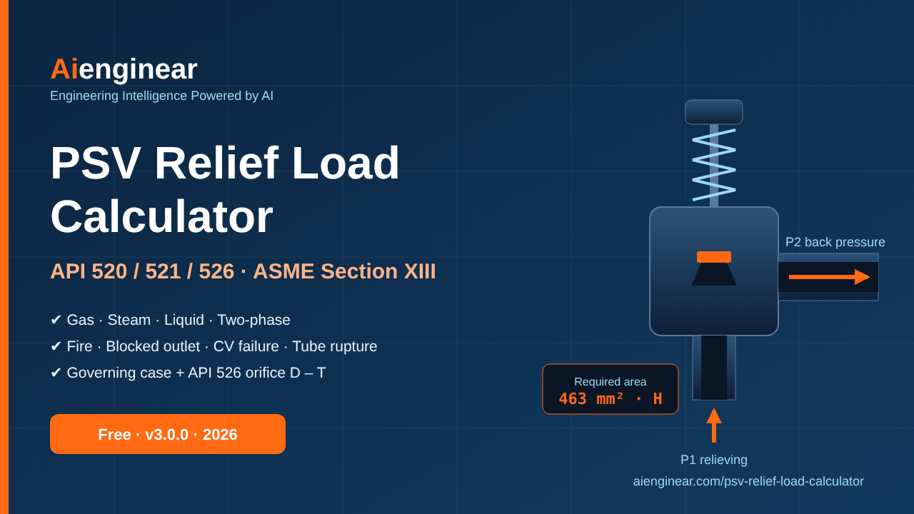
To size a pressure safety valve, find the relief load for every credible overpressure scenario (API 521), convert the set pressure to the relieving pressure by adding the allowable overpressure and atmospheric pressure (ASME Section XIII), calculate the required effective area with the API 520 equation for the fluid phase, then choose the next API 526 orifice letter above the largest area. The free Aienginear calculator below does every step and shows the governing case.
- Gas / vapour: A = W / (C Kd P1 Kb Kc) √(T Z / M) when the flow is choked.
- Liquid: A = 11.78 Q / (Kd Kw Kc Kv) √(G / ΔP), with Kd = 0.65.
- Fire: Q = 43 200 F Aws0.82 W, and the relief load is Q divided by the latent heat; accumulation is 21%.
- Accumulation: 10% for one valve, 16% for several, 21% for fire – with minimums of 20.7 kPa and 27.6 kPa at low set pressures.
- PSV relief load calculator
- How to use the calculator
- How API 520, 521, 526 and ASME XIII fit together
- Set pressure, overpressure and relieving pressure
- Gas and vapour sizing
- Steam sizing
- Liquid sizing and viscosity
- Two-phase relief
- Relief scenarios and loads
- Finding the governing case
- API 526 orifice selection table
- Worked examples
- Back pressure, inlet loss and chatter
- Common sizing mistakes
- What changed in v3.0.0 and how it was verified
- Feature comparison
- FAQ
- Standards and references
- Related Aienginear calculators
- Glossary
1. PSV Relief Load Calculator (API 520 / 521 / 526)
The calculator handles seven relief scenarios – blocked outlet, external fire (wetted, gas-filled and jet fire), thermal expansion, control valve failure, heat-exchanger tube rupture, gas blowby and two-phase flashing relief. It sizes gas, steam, liquid and two-phase service, applies the ASME Section XIII accumulation limit for each scenario automatically, ranks the scenarios you mark as credible, and prints a branded A4 calculation sheet. It runs in your browser; nothing you type is sent to a server.
2. How to Use the Calculator in Six Steps
- Pick the scenario. Start with the overpressure cause you are checking. Each scenario has its own inputs, so you can fill in several and compare them later.
- Enter the set pressure and MAWP in gauge units. Use barg, kPag, psig or MPag. The tool adds the local atmospheric pressure, which you can lower for high-altitude sites. Leave MAWP at 0 if the valve is set at MAWP.
- Keep accumulation on “Auto”. The tool then uses 10% for a single valve, 16% for multiple valves and 21% for fire, with the low-pressure minimums. Switch to manual only for a documented special case.
- Describe the fluid. Choose a fluid from the library or overwrite M, k, Z, density, viscosity or latent heat with values at relieving conditions. For fire, choose the liquid inventory; the matching vapour properties fill in automatically.
- Read the result. You get the required effective area, the flow regime, the API 526 letter, the common inlet and outlet size, the spare capacity and any engineering warnings.
- Confirm the governing case and print. On the Governing Case tab, tick only the scenarios that are credible for your equipment. The largest area governs. Use Print report for a one-page calculation sheet with an approval block.
3. How API 520, API 521, API 526 and ASME Section XIII Fit Together
Relief design draws on four documents, and each one answers a different question. Mixing them up is a common source of error, so it helps to keep the division of work clear.
| Document | Question it answers | What the calculator takes from it |
|---|---|---|
| API Std 521 (7th ed.) | What can cause overpressure, and how much fluid must be relieved? | Fire heat input and wetted-area rules, environmental factors, gas-filled vessel fire, thermal expansion, tube rupture and control-valve failure guidance |
| API Std 520 Part I (10th ed.) | How large must the relief device be for that load? | Effective-area equations for gas, steam, liquid and two-phase (Annex C) flow, and preliminary Kd, Kb, Kc, Kw, Kv, KN |
| API Std 526 (7th ed.) | Which standard flanged valve can I buy? | Orifice letters D to T, effective areas and typical inlet x outlet sizes |
| ASME BPVC Section XIII (2025) | How far may pressure rise while the valve relieves? | Allowable accumulation: 10% / 16% / 21%, with 20.7 kPa and 27.6 kPa minimums |
| API Std 520 Part II | How should the valve be installed? | The 3% inlet-loss and back-pressure checks discussed in Section 13 |
4. Set Pressure, Overpressure, Accumulation and Relieving Pressure
The sizing equations do not use the set pressure. They use the relieving pressure P1: the absolute pressure at the valve inlet when it is passing its full rated flow. P1 is the set pressure plus the allowable overpressure plus atmospheric pressure. Using gauge pressure in a gas equation, or forgetting the overpressure, understates P1 and gives the wrong area.
Accumulation is measured from the vessel’s maximum allowable working pressure (MAWP). If the valve is set below MAWP, the gap between set pressure and MAWP is also available as overpressure, and the calculator uses it when you enter the MAWP.
| Contingency | Number of devices | Maximum accumulation | Low-pressure minimum |
|---|---|---|---|
| Non-fire (blocked outlet, control valve failure, tube rupture and so on) | Single | 10% of MAWP | 20.7 kPa (3 psi) |
| Non-fire | Multiple | 16% of MAWP | 27.6 kPa (4 psi) |
| External fire | Single or multiple | 21% of MAWP | – |
| Supplemental device for fire only | – | 21% of MAWP | – |
5. Gas and Vapour Sizing: Critical and Subcritical Flow
A gas accelerates as it passes through the valve nozzle. If the outlet pressure is low enough, the gas reaches the speed of sound in the throat and the flow chokes: lowering the back pressure further does not increase the flow. Whether this happens depends on the ratio of absolute back pressure to absolute relieving pressure, compared with the critical pressure ratio, which depends only on the ratio of specific heats k.
Critical (choked) flow: A = W / (C Kd P1 Kb Kc) × √(T Z / M)
C = 0.03948 √( k (2 / (k + 1))(k + 1)/(k – 1) )
SI units: A in mm², W in kg/h, P1 in kPa a, T in K, M in kg/kmol. Kd = 0.975 preliminary.
The constant 0.03948 is not a fitted number. It equals 3.6 divided by the square root of the universal gas constant (8 314.46 J/kmol·K) and comes straight from the ideal-gas choked mass flux once the units are converted. The calculator checks this constant, and checks that the area matches a direct isentropic mass-flux calculation, every time the Verification tab is opened.
When the back-pressure ratio is above the critical ratio, the flow is subcritical and depends on the pressure difference. API 520 writes this with a coefficient F2. The calculator uses the same isentropic relation in mass-flux form, which gives the same result and joins smoothly with the choked equation at the critical ratio.
| k = Cp/Cv | Typical gas | Critical ratio Pcf/P1 | C (SI) |
|---|---|---|---|
| 1.05 | Heavy hydrocarbon vapour | 0.5954 | 0.02439 |
| 1.10 | Butane, LPG | 0.5847 | 0.02481 |
| 1.20 | Ethane, light hydrocarbon mix | 0.5645 | 0.02560 |
| 1.30 | Methane, steam, natural gas | 0.5457 | 0.02634 |
| 1.40 | Air, nitrogen, hydrogen | 0.5283 | 0.02703 |
| 1.667 | Helium, argon | 0.4871 | 0.02867 |
With an atmospheric discharge, a typical process valve is choked. Superimposed or built-up back pressure changes that picture. A conventional spring valve set at 10 barg is normally limited to about 10% built-up back pressure. A balanced-bellows valve tolerates much more, but its capacity falls and you must apply the manufacturer’s Kb. A pilot-operated valve handles high back pressure best. The calculator compares gauge back pressure with gauge set pressure – the basis the limits are written on – so a low-set valve discharging to atmosphere is no longer flagged by mistake.
6. Steam Sizing with the Napier Equation
For saturated steam, API 520 keeps the empirical Napier form, which matches steam test data better than the ideal-gas equation:
KN = 1 for P1 ≤ 10 339 kPa a; otherwise KN = (0.02764 P1 – 1000) / (0.03324 P1 – 1061)
A mm², W kg/h, P1 kPa a. The 190.5 constant is the US value 51.5 converted to SI. KSH = 1 for saturated steam.
For superheated steam, use the KSH value from API 520 or the valve maker, or size by the homogeneous direct integration method. Boiler safety valves fall under ASME Section I rules and are outside this tool’s scope.
7. Liquid Relief Sizing and the Viscosity Correction
A mm², Q L/min, G = specific gravity at flowing temperature, P in kPa. Kd = 0.65 for a liquid-certified valve.
The constant 11.78 also comes from first principles: one million divided by sixty thousand (litres per minute to cubic metres per second, and square metres to square millimetres), divided by the square root of two. Liquid valves designed to API 520 reach rated capacity at 10% overpressure, so the liquid equation should only be used with valves certified for liquid service.
Viscosity. Viscous liquids such as fuel oil, crude and caustic need the Kv factor. API 520 calculates it from the Reynolds number on the selected orifice, so the procedure loops: size with Kv = 1, pick the orifice letter, work out Re = 18 800 Q G / (μ √A) with μ in cP and A in mm², calculate Kv = 1 / (0.9935 + 2.878 Re-0.5 + 342.75 Re-1.5), and repeat until the letter stops changing. The calculator does this loop automatically and shows the final Re and Kv. Many competing calculators skip this step and leave Kv at 1.
Back pressure on liquid valves. For balanced-bellows liquid valves, Kw comes from the manufacturer’s curve. For conventional valves, Kw = 1 and the back pressure is already counted in the ΔP term.
8. Two-Phase Relief: the Omega Method
When a liquid flashes as pressure falls through the valve, or when a vessel relieves a froth, gas or liquid equations alone can under-size the device badly. API 520 Annex C describes the omega method. It collapses the flashing behaviour into one compressibility parameter ω and gives a closed-form mass flux.
Critical ratio ηc: η2 + (ω2 – 2ω)(1 – η)2 + 2ω2 ln η + 2ω2(1 – η) = 0
Critical flux: G = ηc √( P0 / (v0 ω) ) Area: A = W / (Kd Kb Kc G), Kd = 0.85
You can enter ω directly – for example from two flash calculations – or let the tool calculate it from inlet quality, specific volumes, liquid heat capacity and latent heat. It also handles subcritical two-phase flow when the back-pressure ratio is above ηc. Treat the result as a screening value. Runaway reactions and other reactive systems need a full DIERS-based analysis.
Earlier versions of this tool applied the gas discharge coefficient (0.975) to two-phase flow. Version 3.0.0 uses the Annex C preliminary value of 0.85, which gives about 15% more area.
9. Relief Scenarios and How Each Load Is Calculated
API 521 asks you to look at every way the equipment could be overpressured and to calculate a relief load for each credible cause. The table below summarises the scenarios the calculator covers and the model it uses for each.
| Scenario | What happens | Load basis in the tool | Accumulation |
|---|---|---|---|
| Blocked outlet | An outlet is closed while feed continues | Maximum inflow you enter (gas, steam or liquid) | 10% / 16% |
| External fire – wetted vessel | A pool fire boils the liquid inventory | Q = C1 F Aws0.82; W = Q / λ | 21% |
| External fire – gas-filled vessel | Fire heats an unwetted wall and the gas inside it | API 521 unwetted-wall relation with wall temperature Tw | 21% |
| Jet fire (screening) | A pressurised release impinges on the vessel | Heat flux x impinged area / λ | 21% |
| Thermal (hydraulic) expansion | Blocked-in liquid is heated by sun or process | q = αv φ / (ρ cp) | 10% / 16% |
| Control valve failure | A valve fails wide open | ISA / IEC flow at rated Cv, minus any normal-outflow credit | 10% / 16% |
| Tube rupture | A tube breaks; high-pressure fluid enters the low-pressure side | Flow through two open tube ends; 10/13 check | 10% / 16% |
| Gas blowby | A level valve opens fully after the liquid is gone | Choked gas flow through the failed valve area | 10% / 16% |
| Two-phase relief | The relieving fluid flashes | Annex C omega method | Scenario-dependent |
9.1 Blocked outlet
The relief load is usually the largest flow the upstream sources can deliver at the relieving pressure – pump curves at the higher discharge pressure, compressor curves, or the full flow from an upstream vessel. Enter that flow in kg/h for gas or steam, or in L/min, m³/h or US gpm for liquid.
9.2 External fire on a wetted vessel
W = 3600 Q / λ (kg/h)
Only the wetted surface within 7.6 m (25 ft) above grade, or above any other surface that could hold a pool fire, counts. In v3.0.0 the wetted area comes from real vessel geometry: diameter, length or height, normal liquid level and elevation of the vessel bottom. The tool cuts off the area above 7.6 m and adds proportional 2:1 elliptical heads. Older versions used fixed dummy dimensions whatever you entered; that has been removed.
Use the latent heat at the relieving pressure. Near the critical point it falls steeply, and a room-temperature value will understate the load. For the vapour, the tool now uses properties of the fluid that is actually boiling (for example propane vapour above liquid propane, or steam above water). Before, the calculation could pair the latent heat of one fluid with the molecular weight of another.
| Protection | Insulation conductance (W/m²·K) | F |
|---|---|---|
| Bare vessel | – | 1.0 |
| Fire-resistant insulation | 22.7 | 0.30 |
| Fire-resistant insulation | 11.4 | 0.15 |
| Fire-resistant insulation | 5.7 | 0.075 |
| Fire-resistant insulation | 3.8 | 0.05 |
| Fire-resistant insulation | 2.8 | 0.0376 |
| Fire-resistant insulation | 2.3 | 0.03 |
| Fire-resistant insulation | 1.9 | 0.026 |
| Water application on a bare vessel | – | 1.0 |
| Depressuring or emptying facilities | – | 1.0 |
| Earth-covered storage above grade | – | 0.03 |
| Below-grade storage | – | 0 |
9.3 Fire on a gas-filled (unwetted) vessel
A vessel holding only gas has no boiling liquid to keep the wall cool. The wall heats quickly and can lose strength before the relief valve does much good. API 521 gives a screening relation for this case:
US: C = 0.1406 (lb/h, psia, ft², °R). The calculator converts this exactly to SI (kg/h, kPa a, m², K). Tw is typically 593 °C for carbon steel.
Published studies have shown that this relation can be non-conservative for wall integrity. That is why API 521 points to depressuring, fire-proofing or water application for gas-filled equipment. The calculator shows that warning whenever this case is selected.
9.4 Thermal (hydraulic) expansion
Liquid trapped between closed valves expands when heated, and because liquids hardly compress, pressure rises very fast. The relief rate is small – q = αv φ / (ρ cp) – and a D orifice or a small thermal relief valve is nearly always enough. What matters is that the valve exists on every isolatable liquid-full section exposed to heat.
9.5 Control valve failure
The relief load is the flow through the valve at its rated (full-open) Cv at maximum upstream pressure and the downstream relieving pressure. Version 3.0.0 replaces the old “18 mm² per Cv” rule of thumb with the ISA-75.01.01 / IEC 60534-2-1 equations. For gas, these use the expansion factor Y and the pressure-drop ratio factor xT, so the choked limit is handled correctly. You can also take credit for normal outflow that stays open during the upset, which API 521 allows.
9.6 Heat-exchanger tube rupture
The usual design basis is a clean break of one tube near the tubesheet. This exposes two open ends, so the flow area is twice the tube cross-section; enter the tube inside diameter and the tool works this out. API 521 lets you exclude the case when the low-pressure side’s corrected hydrotest pressure is at least the high-pressure side’s design pressure. With a hydrotest of 1.3 times design, this is the familiar “10/13 rule”. The tool runs this check from the two design pressures. Liquid-full systems can produce short pressure spikes after a rupture that a relief valve cannot catch; those need a dynamic analysis.
9.7 Gas blowby
If a level-control valve on a high-pressure separator fails open and the liquid drains away, gas flows into the downstream vessel at a rate many times the normal liquid flow. The tool treats this as choked gas flow through the failed valve’s flow area at the upstream pressure. Where the valve’s gas Cv is known, the control-valve-failure scenario gives a better answer.
10. Finding the Governing Relief Case
One vessel can face several overpressure causes. Each gives a different load at a different accumulation, so each needs a different area. The valve has to handle the worst credible single event, so the scenario needing the largest effective area sets the size. API 521 does not normally ask you to combine two unrelated failures happening at the same time (the “double jeopardy” principle). It does, however, require you to include consequences that follow from a single cause – for example, a power failure that stops several pumps at once.
The Governing Case tab lets you tick only the scenarios that are credible for your equipment. Earlier versions ranked every scenario using default inputs, so a default tube-rupture or blowby case could “govern” a vessel that has no exchanger and no level valve. Each scenario now uses its own accumulation – 21% for fire, 10% or 16% for the others – which can change the ranking.
11. API 526 Standard Orifice Selection Table
After calculating the required effective area, pick the smallest API 526 letter whose effective area is equal to or larger than it. API 526 effective areas go with the API preliminary Kd. A manufacturer’s certified capacity uses its own coefficient and actual area. So the final check is always rated capacity (from the maker’s data) against the required load.
| Letter | Effective area (in²) | Effective area (mm²) | Common inlet x outlet (in) |
|---|---|---|---|
| D | 0.110 | 71.0 | 1 x 2 |
| E | 0.196 | 126.5 | 1 x 2 |
| F | 0.307 | 198.1 | 1.5 x 2 |
| G | 0.503 | 324.5 | 1.5 x 2.5 |
| H | 0.785 | 506.5 | 1.5 x 3 |
| J | 1.287 | 830.3 | 2 x 3 |
| K | 1.838 | 1 185.8 | 3 x 4 |
| L | 2.853 | 1 840.6 | 3 x 4 |
| M | 3.60 | 2 322.6 | 4 x 6 |
| N | 4.34 | 2 800.0 | 4 x 6 |
| P | 6.38 | 4 116.1 | 4 x 6 |
| Q | 11.05 | 7 129.0 | 6 x 8 |
| R | 16.00 | 10 322.6 | 6 x 8 |
| T | 26.00 | 16 774.2 | 8 x 10 |
12. Worked Examples
Each example below was solved by hand from the equations in this guide and then reproduced with the calculator to four significant figures. To reproduce one, enter the values in the scenario named.
Example 1 – Propane vapour, blocked outlet
| Item | Value | Working |
|---|---|---|
| Relief load W | 5 000 kg/h | Blocked outlet, gas phase |
| Set pressure = MAWP | 10 barg (1 000 kPa g) | Single valve, 10% accumulation |
| Relieving pressure P1 | 1 201.3 kPa a | 1 000 + 100 + 101.325 |
| Fluid | Propane: M 44.096, k 1.131, Z 0.98, T 60 °C | Atmospheric discharge – choked (critical ratio 0.578) |
| Coefficient C | 0.02506 | 0.03948 √(k (2/(k+1))(k+1)/(k-1)) |
| Required area | 463.5 mm² | 5000 / (0.02506 x 0.975 x 1201.3) x √(333.15 x 0.98 / 44.096) |
| Selected orifice | H (506.5 mm², 1.5 x 3 in) | 9.3% spare capacity |
Example 2 – Horizontal propane drum in a pool fire
| Item | Value | Working |
|---|---|---|
| Geometry | D = 3 m, L = 10 m, liquid level 2 m, bottom 1 m above grade | Whole wetted zone lies below 7.6 m |
| Wetted angle / area | 3.821 rad / 69.19 m² | Shell arc θ R L + proportional 2:1 heads |
| Heat input Q | 1.394 MW | 43 200 x 1.0 x 69.190.82 (bare, adequate drainage) |
| Latent heat at P1 | 320 kJ/kg | Propane near 38 °C saturation |
| Relief load W | 15 684 kg/h | 3600 x 1.394 x 106 / 320 000 |
| Relieving pressure P1 | 1 311.3 kPa a | 1 000 x 1.21 + 101.325 (fire, 21%) |
| Vapour properties | M 44.096, k 1.13, Z 0.80, T 38 °C | Saturated vapour; Z well below 1 |
| Required area | 1 163 mm² | Critical-flow equation |
| Selected orifice | K (1 185.8 mm², 3 x 4 in) | Only 1.9% spare – a borderline selection |
Example 3 – Cooling water, blocked outlet with back pressure
| Item | Value | Working |
|---|---|---|
| Relief flow | 30 m³/h = 500 L/min | Pump capacity at relieving pressure |
| Set pressure / back pressure | 8 barg / 0.5 barg | Back pressure 6.3% of set – acceptable for a conventional valve |
| P1 – P2 | 981.3 – 151.3 = 830 kPa | Both absolute; the old tool used P2 = 0 kPa a here |
| Specific gravity / viscosity | 0.998 / 1.0 cP | Water near 20 °C |
| Required area | 314.4 mm² | 11.78 x 500 / 0.65 x √(0.998 / 830) |
| Reynolds number / Kv | 520 800 / 1.00 | On the G orifice; viscosity has no effect |
| Selected orifice | G (324.5 mm², 1.5 x 2.5 in) | 3.2% spare capacity |
Example 4 – Saturated steam header
| Item | Value | Working |
|---|---|---|
| Relief load | 12 000 kg/h saturated steam | Blocked outlet, Steam (Napier) phase |
| Relieving pressure P1 | 1 751.3 kPa a | 1 500 x 1.10 + 101.325 |
| KN / KSH | 1.0 / 1.0 | P1 below 10 339 kPa a; saturated |
| Required area | 1 339 mm² | 190.5 x 12 000 / (1 751.3 x 0.975) |
| Selected orifice | L (1 840.6 mm², 3 x 4 in) | 37.5% spare; K (1 185.8 mm²) is too small |
13. Back Pressure, Inlet Pressure Loss and Valve Chatter
An area that is right on paper can still fail in service if the installation is poor. Three checks from API 520 Part II and API 521 belong in every PSV calculation:
- Inlet pressure loss. Keep the non-recoverable loss from the vessel to the valve inlet, at rated flow, at or below 3% of set pressure. Otherwise do an engineering analysis of the valve’s stability. A long or undersized inlet line is a main cause of chatter.
- Built-up back pressure. For a conventional valve, keep it within about 10% of set pressure at 10% overpressure. Above that, use a balanced-bellows or pilot-operated valve and the manufacturer’s Kb or Kw curve.
- Oversizing. A valve far larger than the load – for example the L orifice in Example 4 for a small upset – can cycle rapidly at partial load. Where loads vary widely, consider staggered set pressures across several valves or a modulating pilot valve.
The size of the discharge line, and whether the flare header can take the flow, should be checked with a pressure-drop calculation. Aienginear’s Pipe Pressure Drop Calculator can be used for the inlet and tail-pipe losses.
14. Common PSV Sizing Mistakes the Calculator Guards Against
Gauge vs absolute pressure
Gas and steam equations need absolute P1. Gauge units are converted using your site’s atmospheric pressure.
Accumulation applied to absolute pressure
The 10% is a percentage of gauge MAWP, not of absolute pressure. Applying it to absolute pressure overstates P1 by 10 kPa.
Same accumulation for every case
Fire uses 21%; other cases use 10% or 16%. The governing comparison applies each one correctly.
Room-temperature latent heat in fire
Use latent heat and Z at relieving conditions; both fall as you approach the critical point.
Ignoring viscosity
Kv is found automatically by iterating on the selected orifice.
Counting wetted area above 7.6 m
Geometry inputs cut off the area above the pool-fire zone and include the heads.
Back pressure checked against relieving pressure
Back-pressure limits are percentages of gauge set pressure; v3.0.0 uses that basis.
Treating API 526 area as rated capacity
Always confirm the final choice against the maker’s certified capacity.
15. What Changed in v3.0.0 and How It Was Verified
For this release the whole calculation engine was re-audited against the current standards. These corrections change results compared with the previous version:
| Area | Previous behaviour | v3.0.0 |
|---|---|---|
| Pressure basis | Set pressure treated as absolute; zero back pressure meant vacuum | Gauge inputs with site atmospheric pressure; 0 barg = atmospheric discharge (for liquid discharging to atmosphere, the old area was about 6% too small at 8 barg and more than 15% too small at 2 barg) |
| Accumulation | One manual value (default 21%) for every scenario | ASME XIII 10 / 16 / 21% per scenario with 20.7 / 27.6 kPa minimums; MAWP basis |
| Fire wetted area | Vessel-shape options used fixed dummy sizes | Real D, L, level and elevation with the 7.6 m limit |
| Fire fluid pairing | Latent heat of one fluid with vapour properties of another | Vapour properties matched to the boiling liquid |
| Environmental factor | Credit given for depressuring (0.03); some conductances mislabelled | Full API 521 table; F = 0 allowed for below-grade storage |
| Two-phase Kd | Gas Kd 0.975 applied | Annex C Kd 0.85; subcritical two-phase added |
| Control valve failure | 18 mm² per Cv rule of thumb | ISA-75.01.01 / IEC 60534 gas and liquid equations with outflow credit |
| Governing case | Ranked every scenario with default inputs | Only scenarios ticked as credible, each at its own accumulation |
| New scenarios | – | Steam (Napier with KN), gas-filled vessel fire, automatic Kv, tube-rupture two-end area and 10/13 check |
| Usability | Fields lost focus while typing; history could not be reloaded | Typing is uninterrupted; saved cases reload in full; branded A4 print report |
Verification. The calculator has a Verification tab that runs eleven independent checks every time you open it. These include deriving the 0.03948, 11.78, 190.5, 43 200 and 70 900 constants from unit conversion, matching the critical-flow area to a direct isentropic mass-flux calculation to one part in a million, checking that the subcritical and critical equations meet at the critical ratio, the ω = 1 limiting case of the omega method, and the SI form of the unwetted-fire relation against its US original. The four worked examples above were also solved separately in a spreadsheet-style script and match the tool.
16. How This Calculator Compares
| Capability | Typical free calculator | Aienginear v3.0.0 |
|---|---|---|
| Phases | Gas and liquid | Gas, steam (Napier), liquid, two-phase (omega) |
| Relief load generation | You enter the load | Fire (wetted, gas-filled, jet), thermal, control valve failure, tube rupture, blowby |
| Accumulation | Manual | Automatic ASME Section XIII by scenario, with MAWP basis |
| Wetted-area geometry | Rarely | Vertical, horizontal and spherical, with the 7.6 m limit |
| Viscosity correction | Fixed Kv | Automatic API 520 Reynolds iteration |
| Governing case | No | Ranks the credible scenarios |
| Orifice output | Letter only | Letter, area, typical size and spare capacity |
| Report | Screen only | Branded A4 print/PDF, CSV, JSON, history |
| Transparency | Hidden | Formula library, built-in self-test, sensitivity analysis |
| Privacy and cost | Sign-up often required | Free, no sign-up, runs in the browser |
17. Frequently Asked Questions
How do you calculate the relief load for a PSV?
List every credible overpressure cause in API 521 – blocked outlet, fire, control valve failure, tube rupture, thermal expansion, utility failures and so on – and calculate the flow each one produces at relieving conditions. For fire it is the absorbed heat divided by the latent heat. For blocked outlet it is the maximum inflow. For control valve failure it is the flow at the valve’s rated Cv. The largest required area sets the valve size.
What is the difference between API 520, API 521 and API 526?
API 521 defines the overpressure scenarios and how to calculate relief loads. API 520 Part I gives the equations that turn a load into a required effective orifice area. API 526 lists the standard flanged valve orifice letters, D to T, used to buy a real valve. API 520 Part II covers installation.
Is relieving pressure the same as set pressure?
No. Relieving pressure is the set pressure plus the allowable overpressure, plus atmospheric pressure when the equation needs absolute pressure. For a single valve on a non-fire case it is usually 110% of set in gauge terms. For fire it is 121%.
What accumulation is allowed for the fire case?
ASME BPVC Section XIII allows accumulation up to 21% of MAWP for external fire on unfired pressure vessels, compared with 10% for a single device and 16% for multiple devices in non-fire cases.
Why is the fire constant 43 200 or 70 900?
They are the SI forms of the API 521 constants 21 000 and 34 500 (BTU/h with area in ft²). 43 200 applies where there is adequate drainage and prompt firefighting. 70 900 applies where there is not. The heat input is C1 F Aws0.82 in watts.
When is gas flow through a relief valve choked?
When the absolute back pressure is below the critical pressure ratio times the relieving pressure. The ratio is about 0.53 for air and 0.55 to 0.59 for hydrocarbons. Below it, the nozzle throat is sonic and the critical-flow equation applies. Above it, use the subcritical form.
What discharge coefficient should I use?
For preliminary sizing, API 520 suggests Kd = 0.975 for gas, vapour and steam, 0.65 for liquid, and 0.85 for two-phase flow, with Kc = 0.9 when a rupture disk is installed upstream. For final selection, use the manufacturer’s certified coefficient with its actual orifice area.
Do I need a viscosity correction for liquid relief?
Yes, for viscous liquids. Calculate the Reynolds number on the selected orifice and apply Kv. The correction usually matters below Re of roughly 100 000 and can add a full orifice size for heavy oils. The calculator iterates Kv automatically.
When can tube rupture be excluded?
API 521 allows it when the low-pressure side’s corrected hydrotest pressure is at least equal to the high-pressure side’s design pressure. With a 1.3 hydrotest factor, this is the traditional 10/13 rule. Confirm with the actual test pressures and keep the dynamic-transient caution in mind for liquid-full systems.
Can I use this calculator for final valve selection?
Use it for preliminary sizing, studies and checking. Final selection needs the maker’s certified capacity, verified loads, the inlet-loss and back-pressure checks, and review by a qualified engineer under the code editions that apply to the project.
18. Standards and References
- API Standard 520, Sizing, Selection, and Installation of Pressure-relieving Devices, Part I – Sizing and Selection (10th ed.), and Part II – Installation. American Petroleum Institute. api.org
- API Standard 521, Pressure-relieving and Depressuring Systems (7th ed., 2020). American Petroleum Institute.
- API Standard 526, Flanged Steel Pressure-relief Valves (7th ed., 2017). American Petroleum Institute.
- ASME Boiler and Pressure Vessel Code, Section XIII, Rules for Overpressure Protection (2025 ed.), and Section VIII Division 1. The American Society of Mechanical Engineers.
- ISO 4126 series, Safety devices for protection against excessive pressure (Parts 1, 7 and 10 for valves, common data and two-phase sizing).
- ANSI/ISA-75.01.01 / IEC 60534-2-1, Flow equations for sizing control valves.
- Leung, J. C., the omega method for two-phase flow, as adopted in API 520 Part I Annex C; and DIERS project methodology (AIChE).
This guide paraphrases and applies the published methods; it does not reproduce the standards. Buy the current editions from the publishers for authoritative text, tables and limits.
19. Related Aienginear Calculators and Guides
Tube Rupture Relief Valve Suite
Detailed exchanger tube-rupture loads, including dynamic effects.
Control Valve Sizing Calculator
Rated Cv and xT for the control-valve-failure case.
Pressure Vessel Calculator
Confirm MAWP and shell thickness of the protected vessel.
Two-Phase Separator Sizing
Separator geometry and levels for fire wetted area and blowby.
Heat Exchanger Sizing Calculator
Shell and tube data for the rupture scenario.
Pipe Pressure Drop Calculator
Check the 3% inlet loss and built-up back pressure.
Steam Pipe Sizing Calculator
Size steam headers and safety-valve discharge lines.
Hydrotest Pressure Calculator
Test pressures for the 10/13 tube-rupture check.
Vessel Volume Calculator
Liquid inventory and partial-fill levels for fire cases.
Orifice Plate Flow Calculator
Restriction orifices that limit blowby and inflow.
Pressure Integrity & Safety Hub
All of Aienginear’s pressure-safety tools in one place.
All Engineering Calculators
The full Aienginear calculator library.
20. Glossary
| Term | Meaning |
|---|---|
| Accumulation | Pressure rise above MAWP while the device relieves, as a percentage of MAWP. |
| Overpressure | Pressure rise above set pressure during relief. |
| Relieving pressure (P1) | Absolute inlet pressure at rated flow: set + overpressure + atmospheric. |
| MAWP | Maximum allowable working pressure of the protected equipment. |
| Blowdown | Difference between set pressure and reseating pressure. |
| Superimposed / built-up back pressure | Outlet pressure before the valve opens / pressure created by flow in the discharge system. |
| Effective area | Nominal area used with API preliminary coefficients; listed by letter in API 526. |
| Kd, Kb, Kw, Kc, Kv, KN, KSH | Discharge, gas back-pressure, liquid back-pressure, rupture-disk combination, viscosity, Napier high-pressure and superheat correction factors. |
| Choked (critical) flow | Sonic flow at the nozzle throat; flow no longer rises as back pressure falls. |
| Environmental factor F | Fire-case credit for fire-resistant insulation or earth cover. |
| Wetted area | Surface wetted by liquid within 7.6 m of grade, used in the pool-fire equation. |
| Omega (ω) | Two-phase compressibility parameter in the API 520 Annex C method. |
| Governing case | The credible scenario that needs the largest relief area. |

Written by Muhammad Raza
Founder of Aienginear. Engineering and digital solutions professional with 26+ years managing projects, plant shutdowns and turnarounds in oil & gas, petrochemical and power generation.