
AIENGINEAR CALCULATOR · TANKS & VESSELS
Quick answer: how do you calculate tank volume?
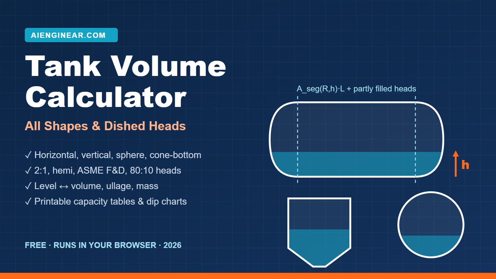
Tank volume is the integral of the tank’s internal cross-sectional area over the liquid depth. For a vertical cylinder that collapses to V = π·(D/2)²·h. For a horizontal cylinder use the circular-segment area times the shell length, V = [R²·acos((R−h)/R) − (R−h)·√(2Rh−h²)]·L, then add the partly filled heads. For a sphere use the spherical cap, V = π·h²·(3R−h)/3.
The free Aienginear Tank Volume Calculator below does this for 11 geometry families and 10 head types, in both directions (level → volume and volume → level), and prints a branded capacity table. It gives theoretical geometric volume, not a certified calibration.
Key takeaways
- Level is proportional to volume only in a straight-sided vertical tank. A horizontal cylinder at 25 % depth holds 19.55 % of its shell volume; a sphere at 25 % depth holds 15.625 %.
- On a bullet with L/D = 3.2, two 2:1 elliptical heads hold about 9.4 % of the total capacity, and they are only partly full at partial level.
- Capacity scales with D², so a 2 % diameter error is about a 4 % capacity error.
- Gross geometric, net (after deadwood) and working volume are three different numbers. Report them separately.
- For custody transfer and fiscal measurement use a certified capacity table to API MPMS Chapter 2 or ISO 7507 / ISO 12917, not a geometric calculation.
How to use the calculator
- Choose the geometry. Pick a family in the visual selector: vertical tank, horizontal vessel, sphere, cone or frustum, elliptical, obround, rectangular or composite.
- Enter internal dimensions. Set the length unit once in the toolbar. Changing it converts the values you already typed instead of relabelling them.
- Select the heads. Use a preset (2:1 elliptical, hemispherical, ASME F&D, 80:10) or enter your own crown, knuckle or depth, plus any straight flange.
- Set the fill. Enter a level, a target volume or a percentage full. The last two are solved backwards to a level.
- Add the liquid. Pick a library liquid or type your own density and its reference temperature to get mass and weight.
- Open Advanced only when needed: external dimensions with wall thickness, deadwood, operating levels (LL to HH), tilt, thermal factor and tolerances.
- Read every warning, then generate the capacity table, fill chart and report, and export CSV, JSON or a project file that reproduces the run.
Shapes and heads covered
Most free tank calculators stop at a cylinder, a rectangle and maybe a cone, and treat heads as either full or empty. The Aienginear tool covers the shapes that actually appear on plot plans, and it keeps visually similar shapes apart because their equations differ.
Aienginear Table 1
Tank geometries and partial-fill method
The 11 geometry families in the calculator and how each partial volume is obtained
| Geometry family | Typical service | Partial-fill method |
|---|---|---|
| Vertical cylinder (flat, dished or cone bottom/roof) | Atmospheric storage, process and dosing tanks | Linear in the shell; closed-form or numerical in the heads |
| Horizontal cylinder with heads | Bullets, separators, KO drums, fuel tanks | Circular segment in the shell; slice integration in the heads |
| Sphere | LPG, butane, ammonia storage | Closed-form spherical cap |
| Cone and frustum (hopper) | Silos, hoppers, cone-bottom tanks | Closed-form frustum to the liquid surface |
| Horizontal ellipse | Road tankers, skid tanks | Closed form: (a/b) × circular segment |
| Vertical ellipse | Space-limited vertical tanks | Linear: π·a·b·h |
| Obround / stadium | Fuel and transport tanks | Rectangle band plus two circular segments |
| Horizontal capsule (hemispherical ends) | Small pressurised receivers | Circular segment plus closed-form spherical cap |
| Vertical capsule (hemispherical ends) | Air receivers, vertical accumulators | Spherical cap, linear shell, spherical cap |
| Rectangular / cuboid | Sumps, pits, IBCs, day tanks | Linear: L·W·h |
| Composite stack | Any user-built vessel | Section by section, cumulative and continuous |
How tank volume is calculated
Every tank, however odd its shape, is handled the same way: integrate the area of the liquid surface’s horizontal slices from the bottom of the tank to the liquid level. Where the cross-section is constant, that integral is simply area × height. Where it changes with depth, the change has to be carried through the arithmetic, and that is exactly where hand calculations and simple online tools go wrong.
- Use internal dimensions. If the drawing shows outside diameter, subtract twice the wall thickness first.
- Break the tank into sections: bottom head or cone, shell, top head or roof. Each has its own volume equation.
- Locate the liquid surface. Sections below it are full; the section it cuts is partly full; sections above are empty.
- Apply the partial-fill equation to the cut section only.
- Sum the sections, then add or subtract deadwood if required.
- Convert units and, for mass, multiply by the density at its stated reference temperature.
Tank volume formulas
The table below collects the closed-form equations used by the calculator. Symbols: D inside diameter, R = D/2 inside radius, L shell length, h liquid depth (or head depth where noted), a and b the horizontal and vertical semi-axes of an ellipse, r₁ and r₂ the large and small radii of a frustum.
Aienginear Table 2
Tank volume formulas: full and partial fill
Internal dimensions, consistent units
| Shape | Full volume | Volume at liquid depth h |
|---|---|---|
| Vertical cylinder | π·R²·H | π·R²·h |
| Horizontal cylinder | π·R²·L | A_seg(R,h)·L |
| Circular segment area | – | A_seg = R²·acos((R−h)/R) − (R−h)·√(2Rh − h²) |
| Sphere | (4/3)·π·R³ | π·h²·(3R − h)/3 |
| Cone, apex down | (π/3)·R²·H | (π/3)·(R·h/H)²·h |
| Frustum (hopper) | (π·H/3)·(r₁² + r₁r₂ + r₂²) | Frustum from r₂ to r(h) = r₂ + (r₁−r₂)·h/H |
| Rectangular | L·W·H | L·W·h |
| Horizontal ellipse | π·a·b·L | (a/b)·A_seg(b,h)·L |
| Hemispherical head | (2/3)·π·R³ | Spherical cap (vertical) / slice integral (horizontal) |
| 2:1 elliptical head | π·D³/24 | Ellipsoid integral / slice integral |
| Ellipsoidal head, depth hd | (2/3)·π·R²·hd | Ellipsoid integral / slice integral |
| Spherical dish, depth hd | π·hd·(3R² + hd²)/6 | Cap integral / slice integral |
| Conical head, depth hd | (π/3)·R²·hd | Frustum to the surface |
| Torispherical head | No simple closed form | Numerical integration (crown + knuckle) |
Horizontal tank volume
A horizontal cylinder filled to depth h holds A_seg(R, h) × L in its shell. The relationship is S-shaped: volume rises slowly near the bottom, fastest at the centreline, and slowly again near the top. Only at exactly half the diameter does percentage depth equal percentage volume.
V_shell(h) = A_seg(R,h) · L
That S-curve is why a straight-line dip chart overstates inventory in the lower half of a bullet and understates it in the upper half. At 25 % of the diameter the shell is 19.55 % full; at 75 % it is 80.45 % full.
Aienginear Table 3
Percent depth to percent volume: horizontal cylinder and sphere
Horizontal cylinder = shell only (flat ends). Valid for any diameter.
| Depth, % of D | Horizontal cylinder, % volume | Sphere, % volume | Linear assumption, % volume |
|---|---|---|---|
| 5 | 1.87 | 0.725 | 5 |
| 10 | 5.20 | 2.800 | 10 |
| 20 | 14.24 | 10.400 | 20 |
| 25 | 19.55 | 15.625 | 25 |
| 30 | 25.23 | 21.600 | 30 |
| 40 | 37.35 | 35.200 | 40 |
| 50 | 50.00 | 50.000 | 50 |
| 60 | 62.65 | 64.800 | 60 |
| 70 | 74.77 | 78.400 | 70 |
| 75 | 80.45 | 84.375 | 75 |
| 80 | 85.76 | 89.600 | 80 |
| 90 | 94.80 | 97.200 | 90 |
| 95 | 98.13 | 99.275 | 95 |
Heads complicate the picture further. Below the top of the vessel, each head is only partly full, and every axial slice through a head is a smaller circle than the shell. The calculator integrates the circular-segment area of those slices through each head, so the head contribution grows smoothly with level rather than switching between zero and full.
Vertical and cone-bottom tank volume
A flat-bottomed vertical cylinder is the simple case: V = π·(D/2)²·h, a straight line from empty to full. That is why API 650 storage-tank gauge tables are nearly linear over the shell.
The ends spoil the straight line. With a cone or hopper bottom, the liquid fills the cone first and the level climbs quickly for very little volume; once the cone is full, the volume per millimetre steps up to the shell rate. A dished roof does the reverse near the top. The calculator models the tank as an ordered stack of sections and keeps the cumulative curve continuous across each tangent line.
A hopper that ends in a 200 mm outlet is a frustum, not a cone. The calculator takes the outlet radius as an input instead of forcing it to zero, which matters at low level in dosing and chemical-injection tanks.
Spherical tank volume
A sphere holds (4/3)·π·R³ and its partial volume is the spherical cap π·h²·(3R − h)/3. It is the most non-linear common shape: only 15.625 % full at a quarter of the diameter and 84.375 % full at three quarters. Spheres are favoured for LPG, propane, butane and ammonia because they have the least surface per unit volume and an even membrane stress; in service they are gauged against a certified capacity table.
Tank head volume
Heads are where capacity quietly appears or disappears. The table gives depth and full volume for each head the calculator supports, on an inside-dimension basis and without straight flange. A straight flange is added separately as a short cylinder, π·R²·SF, so a tangent-to-tangent length from the drawing is never double-counted.
Aienginear Table 4
Tank head depth and volume by head type
One head, inside diameter D, no straight flange
| Head type | Geometry | Inside depth | Volume of one head | Method |
|---|---|---|---|---|
| Flat | Plate | 0 | 0 | – |
| Hemispherical | Half sphere | 0.500·D | 0.2618·D³ | Closed form, π·D³/12 |
| 2:1 semi-elliptical | Semi-ellipsoid, a/b = 2 | 0.250·D | 0.1309·D³ | Closed form, π·D³/24 |
| User-defined elliptical | Any depth hd | hd | (π/6)·D²·hd | Closed form |
| ASME flanged & dished | Crown R = D, knuckle r = 0.06·D | ≈ 0.169·D | ≈ 0.0810·D³ | Numerical integration |
| 80:10 torispherical | Crown R = 0.8·D, knuckle r = 0.1·D | ≈ 0.226·D | ≈ 0.1099·D³ | Numerical integration |
| User-defined torispherical | Any crown and knuckle | L − √[(L−r)² − (D/2−r)²] | – | Numerical integration |
| Spherical dish | Crown only, no knuckle | hd | π·hd·(3R² + hd²)/6 | Closed form |
| Conical / frustum | Half-apex angle α, optional outlet | (R − r₂)/tan α | Frustum equation | Closed form |
Rule of thumb: on a horizontal bullet, two 2:1 heads add a volume equal to D/3 of extra shell length (2 × π·D³/24 = π·R²·D/3). That is a quick way to sanity-check any head calculation.
Elliptical, obround and capsule tanks
These three shapes look alike on a sketch and are confused constantly in road-tanker and skid-tank work. They need different equations:
- Elliptical cross-section: one smooth curve, width 2a and height 2b. Because an ellipse is a stretched circle, the filled area at depth h is (a/b) × the segment area of a circle of radius b. That is exact, not an approximation.
- Obround (stadium): a rectangle closed by two semicircles. The filled area is a rectangular band plus two circular segments.
- Capsule: a cylinder with hemispherical ends. Here the curvature runs along the axis, so a horizontal capsule is a circular-segment shell plus the two ends combined into one spherical cap.
Partial fill: exact equations vs numerical integration
The calculator uses a closed-form equation wherever one exists: the circular segment, the spherical cap, the frustum to the surface and the ellipsoid integral. Two cases have no practical closed form: torispherical heads, and any dished head lying on its side in a horizontal vessel. For those the engine applies composite 8-point Gauss–Legendre quadrature, doubling the number of panels until successive estimates agree to a relative 1×10⁻¹².
Each result is labelled as analytical, numerical integration, numerical root solution or a combination. A method that fails to converge stops and reports its residual instead of returning a number. Note that this tolerance describes arithmetic only. It says nothing about how well your entered dimensions match the steel; that is handled separately in the tolerance panel.
Volume to level is the inverse problem, and for curved shapes it has no closed form. The tool solves it by safeguarded bisection on the monotonic V(h) curve and shows iterations, residual and tolerance so you can see it converged.
Capacity, working volume and ullage
Geometric capacity is what the steel encloses. Working volume is what the process can use between its low and high operating levels. They are never the same number, and the calculator never merges them into one ambiguous “capacity”.
Ullage (outage) is the empty space above the liquid, as a volume or a height. It tells you how much more product the tank can receive before a transfer. Enter LL, L, N, H and HH in the Advanced panel and the calculator reports working volume, heel and operating ullage beside the geometric capacity, clearly labelled as process limits rather than geometry.
Gross vs net tank volume and deadwood
Gross geometric volume ignores what is inside the tank. Net volume accounts for it. Calibration practice calls these items deadwood, and it works in both directions:
- Negative deadwood displaces liquid: heating coils, mixers, agitators, columns, internal structures.
- Positive deadwood adds space: sumps, bottom bulges, manway barrels and nozzle projections that hold liquid.
Position matters, so each item gets an elevation model: at the bottom datum, effective above a stated elevation, in the vapour space, or spread uniformly over the height. The uniform option is labelled a screening approximation for when you do not know the elevation. The tool reports gross geometric capacity, net capacity, liquid geometric volume and liquid net volume as four separate numbers.
Do not confuse deadwood with dead volume, which is liquid that cannot be withdrawn, typically below the outlet nozzle or pump minimum level.
Tank capacity tables and dip charts
A capacity table (gauge table, dip chart, strapping table) lists volume against level at fixed increments. The calculator builds one at any step from 1 mm or 1 inch, or at a fixed number of rows, on one of three bases:
- Gross geometric (reference): what the shell encloses, no deadwood, no thermal factor. The classic theoretical table.
- Net effective (reference): the same table with the same deadwood items and elevation models as the main result.
- Net effective (operating temperature): the net table multiplied by your user-defined shell-expansion factor; available only when that correction is on.
Percentage, ullage and mass follow the selected basis, and every column header names it. Before export the table is validated: zero at the datum, total capacity at the top, monotonic volume, no negative or out-of-range values, and continuity across section boundaries. Each check shows PASS or FAIL, and a table that fails is not exported. If a simplified deadwood model makes the curve step down (so one volume occurs at two levels), the tool says so and refuses both the export and the inverse solve rather than guessing.
Columns exported to CSV: level, percentage full, liquid volume, ullage volume, ullage height and liquid mass, in your chosen units, with the basis in the file metadata.
Calculated volume vs certified tank calibration
This calculator gives theoretical geometric volume. A certified capacity table measures the tank that was actually built. The difference can be well under 1 % on a good new tank and considerably more on an old, settled or deformed one.
Aienginear Table 5
Geometric calculation vs certified tank calibration
Choose the right tool for the decision you are making
| Aspect | Geometric calculation (this tool) | Certified calibration |
|---|---|---|
| Input | Nominal internal dimensions from drawings or data sheets | Measurements of the real tank |
| Methods | Closed-form geometry and numerical integration | Manual strapping, optical reference line, electro-optical distance ranging, liquid calibration, 3D laser scanning |
| Captures | Ideal shape, entered deadwood | Actual course circumferences, out-of-roundness, tilt, bottom shape, deadwood, shell temperature |
| Governing documents | Solid geometry | API MPMS Chapter 2; ISO 7507 series; ISO 12917 series |
| Use for | Design, sizing, screening, operations support, checking, training | Custody transfer, fiscal measurement, inventory reconciliation, regulatory reporting |
| Output status | Theoretical, uncertified | Certified capacity table with stated uncertainty |
Worked examples
Example 1: horizontal crude oil vessel with 2:1 elliptical heads
Inside diameter 2,500 mm, shell 8,000 mm tangent to tangent, two 2:1 semi-elliptical heads, light crude at 850 kg/m³. All values below were reproduced independently from the equations in Table 2 and agree with the calculator engine.
Aienginear Table 6
Worked example 1: horizontal vessel, D 2.5 m × L 8.0 m, 2:1 heads
Light crude, 850 kg/m³ · capacity 43.361 m³
| Quantity | Value | Note |
|---|---|---|
| Shell volume | 39.270 m³ | π·1.25²·8.0 |
| Two 2:1 heads | 4.091 m³ | 2·π·2.5³/24; 9.4 % of capacity |
| Total capacity | 43.361 m³ | 272.7 bbl · 11,455 US gal |
| Level 1,250 mm (centreline) | 21.680 m³ | 50.00 % full · 18.43 t · 136.4 bbl |
| Level 500 mm: shell | 5.591 m³ | Circular segment × L |
| Level 500 mm: both heads | 0.425 m³ | Slice integration; full heads hold 4.091 m³ |
| Level 500 mm: liquid volume | 6.017 m³ | 13.88 % full · 5.11 t · 37.8 bbl |
| Wrong method: partial shell + full heads | 9.682 m³ | 61 % too high |
Example 2: vertical cone-bottom process tank
Inside diameter 2,400 mm; 1,200 mm deep hopper ending in a 200 mm outlet; 4,000 mm cylindrical shell; 2:1 elliptical top head; water at 1,000 kg/m³.
Aienginear Table 7
Worked example 2: cone-bottom tank, D 2.4 m, 1.2 m hopper
Water, 1,000 kg/m³ · capacity 21.878 m³ · total height 5,800 mm
| Quantity | Value | Note |
|---|---|---|
| Hopper (frustum) | 1.973 m³ | (π·1.2/3)·(1.2² + 1.2·0.1 + 0.1²) |
| Cylindrical shell | 18.096 m³ | π·1.2²·4.0 |
| 2:1 top head | 1.810 m³ | π·2.4³/24 |
| Total capacity | 21.878 m³ | 5,780 US gal |
| Level 1,200 mm (top of hopper) | 1.973 m³ | 9.02 % of capacity at 20.7 % of height |
| Level 2,200 mm | 6.497 m³ | 29.70 % full · 6.497 t water |
| Wrong method: whole tank as a cylinder | 9.953 m³ | 53 % too high |
Volume units and conversions
The calculator works in litres, cubic metres, US gallons, Imperial gallons, cubic feet, US oil barrels and cubic inches. US and Imperial gallons are always labelled and never converted silently: an Imperial gallon is about 20 % larger than a US gallon.
Aienginear Table 8
Tank volume unit conversions
Exact by definition unless marked ≈
| Unit | Litres | Per 1 m³ |
|---|---|---|
| Cubic metre (m³) | 1,000 | 1 |
| US gallon | 3.785411784 | ≈ 264.172 |
| Imperial gallon | 4.54609 | ≈ 219.969 |
| US oil barrel (42 US gal) | 158.987294928 | ≈ 6.28981 |
| Cubic foot | 28.316846592 | ≈ 35.3147 |
| Cubic inch | 0.016387064 | ≈ 61,023.7 |
Oil and gas and industrial applications
- Production and stock tanks: gauge readings to barrels for allocation and daily production reports.
- Separators, KO drums and surge vessels: holdup and residence time between control and trip levels in horizontal vessels with dished heads. Pair with the Two-Phase Separator Sizing Calculator.
- Terminal and refinery storage: capacity checks, ullage before a receipt, and screening against the calibrated table.
- LPG bullets and spheres: fill limits and inventory at a measured level, where the curve is most non-linear.
- Slop, drain and closed-drain drums: available volume before overflow.
- Firewater and utility tanks: effective volume above the pump minimum submergence level, not nominal capacity.
- Hydrotest planning: fill water volume and the load the foundation will carry; continue with the Hydrotest Calculator.
- Dosing and chemical-injection tanks: usable volume above the hopper outlet; see the Chemical Dosing & Flushing Calculator.
- Shutdowns and turnarounds: drain-down, flushing and refill volumes for planning, as covered in our turnaround and shutdown guide.
Common tank volume calculation mistakes
- Treating depth as proportional to volume in a horizontal vessel or sphere. At 25 % depth a bullet shell holds 19.55 %, not 25 %.
- Adding full heads to a partly filled shell. In Example 1 that overstates the contents by 61 % at a 500 mm level.
- Using outside dimensions. Capacity is an inside quantity; on small vessels the wall is not negligible.
- Mixing US and Imperial gallons. They differ by about 20 %.
- Calling an obround or capsule an ellipse. Different shapes, different equations.
- Ignoring the cone in a cone-bottom tank, or adding it as full at every level.
- Forgetting the straight flange on dished heads, or counting it twice.
- Ignoring deadwood from coils, mixers and internals, or spreading it evenly without saying so.
- Mismatched level datum. A radar gauge referenced to a nozzle or a striker plate is not measuring from the lowest internal point.
- Presenting a geometric volume as a calibrated capacity in custody-transfer work.
- False precision. Twelve significant figures from a diameter measured to ±10 mm is not more accurate, just less honest.
How this calculator compares
Aienginear Table 9
Aienginear Tank Volume Calculator vs typical free online tank calculators
Feature comparison, October 2026
| Feature | Typical free calculator | Aienginear |
|---|---|---|
| Geometry families | 3 to 8 basic shapes | 11 families, including ellipse, obround, capsule and composite stacks |
| Head types | Flat or none; sometimes hemi and 2:1 | 10 types incl. ASME F&D, 80:10 and user-defined torispherical, plus straight flange |
| Partly filled heads on horizontal vessels | Often treated as full or ignored | Integrated slice by slice |
| Volume or % full to level | Rare | All geometries, with convergence report |
| Capacity table / dip chart | Rare, unvalidated | Any increment, three bases, PASS/FAIL validation, CSV |
| Deadwood and operating levels | No | Positive and negative deadwood with elevation models; LL to HH working volume |
| Method transparency | Answer only | Equation or numerical method shown for every result |
| Reports and files | Copy the number | Printable report, CSV, JSON, reproducible project file |
| Self-test | No | Built-in benchmark suite with expected vs actual |
| Privacy | Varies; often ad-tracked forms | Runs entirely in your browser |
Engineering standards and references
This is a geometric volume calculator. The documents below are cited for terminology, methodology and design context. No compliance with any of them is claimed or implied.
Aienginear Table 10
Tank standards: current editions and how they relate to volume
Status checked against publisher information, October 2026
| Document | Subject | Edition / status | Role on this page |
|---|---|---|---|
| API Std 650 | Welded tanks for oil storage | 14th edition, August 2025; Monogram effective 1 March 2026 | Design context |
| API Std 620 | Large, welded, low-pressure storage tanks | 12th edition (2013) with addenda | Design context |
| API Std 653 | Tank inspection, repair, alteration, reconstruction | 5th edition (2014), Addendum 4, July 2025 | Inspection context |
| API RP 575 | Inspection of atmospheric and low-pressure tanks | 5th edition, September 2024, Addendum 2, June 2026 | Inspection context |
| API Spec 12F, 12B; API RP 12R1 | Production-service tanks | Current editions | Design context |
| API Std 625 | Refrigerated liquefied gas tank systems | Current edition | Design context |
| ASME BPVC Section VIII, Div. 1 & 2 | Pressure vessels, incl. ellipsoidal and torispherical heads | 2025 edition | Head geometry |
| API MPMS Chapter 2 | Tank calibration (2.2A upright tanks by manual strapping; 2.2E horizontal tanks) | 2.2A: 2nd edition, November 2019 | Calibration methodology |
| API MPMS Chapters 3 and 12 | Tank gauging; calculation of petroleum quantities | Current editions | Measurement context |
| ISO 7507 series | Calibration of vertical cylindrical tanks | Parts 1 to 6 published | Calibration methodology |
| ISO/DIS 7507-7 | 3D scanning and point-cloud processing | Draft International Standard registered 12 October 2026; not yet published | Watch item |
| ISO 12917-1:2017 + Amd 1:2025 | Calibration of horizontal cylindrical tanks, manual methods | Current; amendment 2025 | Calibration methodology |
Design standards say how a tank is designed, built and inspected. Calibration and measurement documents say how the capacity of an existing tank is established and how a gauged level becomes a quantity. Neither group is implemented in this tool. Tank mechanical design (shell thickness, roof, foundation, wind and seismic) is deliberately kept out of the volume engine; for pressure-vessel wall thickness use the ASME VIII Pressure Vessel Calculator.
Assumptions and limitations
- Theoretical geometric volume only; not a certified calibration and not a custody-transfer quantity.
- Fabrication tolerance, out-of-roundness, shell bulging, bottom settlement, lining, insulation and corrosion allowance are not modelled.
- Tilt is a screening model for horizontal cylinders with flat ends and vertical cylinders with the surface in the shell, up to 15°. Forward and inverse calculations use the same corrected-centreline model; other tilted cases are refused, not approximated.
- Simplified deadwood elevation models introduce steps in the level/volume curve and are labelled as such.
- The thermal factor is a user-defined shell-expansion multiplier, not an API MPMS Chapter 11 or 12 temperature correction. Mass is conserved when density is entered at the reference temperature.
- Library densities are illustrative and are not for fiscal use.
- Floating roofs, internal floating decks and modelled internals are not included.
Video explainer
Quick quiz: test your tank volume knowledge
1. A horizontal cylinder (flat ends) is filled to 25 % of its diameter. How full is it by volume?
2. What is the inside depth of a 2:1 semi-elliptical head?
3. If the inside diameter is 5 % larger than assumed, the cylinder capacity is about…
4. A heating coil inside a tank is an example of…
5. For custody transfer you should use…
Related Aienginear calculators and guides
Frequently asked questions
How do you calculate tank volume?
Split the tank into sections of known shape (bottom head or cone, shell, top head), add the full volume of every section below the liquid surface, add the partial volume of the section the surface cuts, then add or subtract deadwood. For a flat-bottomed vertical cylinder this reduces to V = π·(D/2)²·h.
How do you calculate the volume of a horizontal cylindrical tank?
Multiply the circular-segment area A = R²·acos((R−h)/R) − (R−h)·√(2Rh − h²) by the shell length, then add the partly filled volume of each head. Never scale total capacity by percentage depth: at 25 % depth a horizontal shell is only 19.55 % full.
How do you calculate the volume of a partially filled tank?
Use the partial-fill equation for the shape at the liquid surface: circular segment for a horizontal cylinder, spherical cap for a sphere, frustum to the surface for a cone, and numerical integration for torispherical heads or dished heads on a horizontal vessel. The Aienginear calculator shows which method it used.
What is the formula for the volume of a cylindrical tank?
A full cylinder holds V = π·(D/2)²·L. Partly filled, a vertical cylinder holds π·(D/2)²·h and a horizontal cylinder holds the circular-segment area at depth h multiplied by the length.
How do you calculate the volume of a spherical tank?
Full volume is (4/3)·π·R³. At liquid depth h the contents are the spherical cap π·h²·(3R − h)/3. At a quarter of the diameter a sphere is only 15.625 % full.
How do you calculate the volume of a cone-bottom tank?
Treat the cone (or frustum, if it has an outlet) and the cylinder as separate sections. Below the cone tangent use the frustum equation with the radius at the liquid surface; above it the cone is full and the shell fills linearly.
What is the volume of a 2:1 elliptical head?
One 2:1 semi-elliptical head has an inside depth of D/4 and a volume of π·D³/24, about 0.1309·D³. Two of them equal the volume of an extra D/3 of shell length.
How do I convert tank level to volume?
Measure the level from the lowest internal point, enter it with the tank dimensions, and the calculator returns liquid volume, ullage, percentage full and mass. For routine use, generate a capacity table at your gauge increment and export it to CSV.
Can I calculate the level from a known volume?
Yes. Enter a target volume or percentage full and the calculator solves the level by safeguarded bisection on the volume curve, reporting iterations, residual and tolerance.
What is the difference between gross capacity and working volume?
Gross capacity is everything the shell encloses. Working volume is the usable volume between the low and high operating levels. The difference is the heel below the low level plus the vapour space above the high level.
What is ullage in a tank?
Ullage, or outage, is the empty space above the liquid, expressed as a volume or a height. It tells you how much more product the tank can receive.
What is deadwood in tank calibration?
Deadwood is any internal item that changes the effective volume. Negative deadwood, such as coils, mixers and internal structures, displaces liquid; positive deadwood, such as sumps or manway barrels, adds space. Dead volume is different: it is liquid below the outlet that cannot be withdrawn.
Can this calculator replace a certified tank calibration?
No. It calculates theoretical volume from entered dimensions. Custody transfer, fiscal measurement and inventory reconciliation need a certified capacity table produced under API MPMS Chapter 2 or the ISO 7507 and ISO 12917 series.
Is the calculator API 650 compliant?
No compliance is claimed. API 650 is a design and construction standard for welded oil storage tanks, not a volume calculation method. It is cited only for design context.
Which units does the tank volume calculator support?
Litres, cubic metres, US gallons, Imperial gallons, cubic feet, US oil barrels and cubic inches for volume, plus kilograms, tonnes, pounds, US tons and long tons for mass. US and Imperial gallons are always labelled separately.
How accurate is the tank volume calculator?
The arithmetic is double-precision with numerical methods converged to a relative 1×10⁻¹², and a built-in self-test compares every geometry against analytical benchmarks. Real-world accuracy is limited by how closely your dimensions match the fabricated tank, not by the arithmetic.
Is my data sent anywhere?
No. All calculations, tables, reports and exports run in your browser. Nothing is sent to a server.
Disclaimer. This calculator supports preliminary engineering, screening, education and design. It returns theoretical geometric volume from the dimensions and geometry you enter. It does not replace certified tank calibration, custody-transfer measurement, manufacturer documentation, project specifications, regulations or review by a qualified engineer. Real capacity differs with fabrication tolerance, deformation, tilt, internals, corrosion, temperature and liquid properties.
Aienginear Tank Volume Calculator: All Shapes & Geometries · calculator, engine and database v1.0.5 · article updated 20 October 2026 · standards status checked October 2026 · Published by Aienginear.com. Found an error? Tell us.

Written by Muhammad Raza
Founder of Aienginear. Engineering and digital solutions professional with 26+ years managing projects, plant shutdowns and turnarounds in oil & gas, petrochemical and power generation.