
Aienginear.com · Piping reference
Long-radius and short-radius 180° return bend dimensions from NPS ½ to 24, in millimetres and inches, checked against ASME B16.9-2024 — with tolerances, inspection checks and a coil layout calculator.
Quick answer
Return bend dimensions come down to two numbers. A 180° return is a buttwelding fitting that turns flow back on itself, and its two governing dimensions are O, the centre-to-centre distance between the legs, and K, the back-to-face projection. Both are set by ASME B16.9:
- Long radius (LR): centreline radius = 1.5 × NPS, so O = 3 × NPS (NPS 1¼ and up). NPS 4 LR: O = 305 mm, K = 210 mm.
- Short radius (SR): centreline radius = 1.0 × NPS, so O = 2 × NPS, available from NPS 1. NPS 4 SR: O = 203 mm, K = 159 mm.
- Rule of thumb: K ≈ (O + OD) ÷ 2 — useful for checking a datasheet in seconds.
- Standard status: short-radius returns were once covered by ASME B16.28; that standard is withdrawn and its content now sits in B16.9.
What is a 180° return bend?
A 180° return — also called a return bend, U-bend fitting or simply a “return” — is a factory-made buttwelding fitting that reverses the direction of a pipe run through a half circle. It is the building block of furnace and heater coils, heat-recovery and jacketed coils, cooling loops, expansion loops in tight racks and any layout where two parallel lines must be joined end to end.
Two terms are often mixed up on drawings and in purchase orders:
- Return (fitting): a standard catalogue fitting made to ASME B16.9, with fixed O and K for each size and radius. This article covers these.
- Pipe bend: a length of straight pipe bent cold or by induction to any radius (commonly 3D or 5D). Pipe bends are designed to the piping code and the purchase specification — for pipeline induction bends, ASME B16.49 — not to the B16.9 dimension tables.
- Two 90° elbows: a field-made alternative that gives the same LR centre-to-centre but adds a girth weld. See our ASME B16.9 pipe elbow dimensions chart for the elbow values.
How return bend dimensions O, K and OD are defined
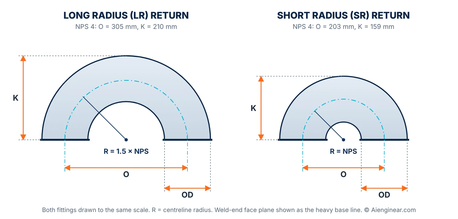
All return bend dimensions in the chart below refer to one of the callouts in Figure 1:
- O — centre-to-centre. Distance between the centrelines of the two legs, measured in the plane of the weld ends. In a coil this is the leg pitch.
- K — back-to-face. Distance from the plane of the weld-end faces to the outermost point on the back of the bend. This is how far the fitting sticks out past the pipe ends.
- OD — outside diameter at the bevel. Matches the pipe OD for the same NPS. NPS is a size label, not a measured diameter: NPS 4 has an OD of 114.3 mm, not 101.6 mm. See the industrial pipe NPS and schedule guide.
- R — centreline radius. Half of O. LR = 1.5 × NPS, SR = 1.0 × NPS (in inches).
Labelling trap: catalogues use different letters for the same thing (some use V and W, others A to D). Always map letters back to centre-to-centre and back-to-face before using a value. This article uses the ASME B16.9 letters O and K throughout.
Return bend finder
Look up any size in one click
Pick a size to see LR and SR dimensions with their ASME B16.9 tolerances, then add schedule and material to generate a ready-to-paste purchase-order line.
Return bend dimensions chart: 180° LR and SR (mm and inches)
Table 1 lists every long-radius and short-radius return size in ASME B16.9. Use the buttons in the table header to switch between mm and inches, print a clean Aienginear-branded copy (or save it as PDF), download the data as CSV, or copy it straight into Excel.
| NPS (in) | DN | OD at bevel | Long radius (LR) | Short radius (SR) | ||
|---|---|---|---|---|---|---|
| O centre-to-centre | K back-to-face | O centre-to-centre | K back-to-face | |||
| ½ | 15 | 21.3 | 76 | 48 | — | — |
| ¾ | 20 | 26.7 | 76 | 51 | — | — |
| 1 | 25 | 33.4 | 76 | 56 | 51 | 41 |
| 1¼ | 32 | 42.2 | 95 | 70 | 64 | 52 |
| 1½ | 40 | 48.3 | 114 | 83 | 76 | 62 |
| 2 | 50 | 60.3 | 152 | 106 | 102 | 81 |
| 2½ | 65 | 73.0 | 190 | 132 | 127 | 100 |
| 3 | 80 | 88.9 | 229 | 159 | 152 | 121 |
| 3½ | 90 | 101.6 | 267 | 184 | 178 | 140 |
| 4 | 100 | 114.3 | 305 | 210 | 203 | 159 |
| 5 | 125 | 141.3 | 381 | 262 | 254 | 197 |
| 6 | 150 | 168.3 | 457 | 313 | 305 | 237 |
| 8 | 200 | 219.1 | 610 | 414 | 406 | 313 |
| 10 | 250 | 273.1 | 762 | 518 | 508 | 391 |
| 12 | 300 | 323.9 | 914 | 619 | 610 | 467 |
| 14 | 350 | 355.6 | 1067 | 711 | 711 | 533 |
| 16 | 400 | 406.4 | 1219 | 813 | 813 | 610 |
| 18 | 450 | 457.0 | 1372 | 914 | 914 | 686 |
| 20 | 500 | 508.0 | 1524 | 1016 | 1016 | 762 |
| 22 | 550 | 559.0 | 1676 | 1118 | 1118 | 838 |
| 24 | 600 | 610.0 | 1829 | 1219 | 1219 | 914 |
— = size not listed for SR returns (B16.9 starts short-radius returns at NPS 1). Millimetre values are the metric values listed in ASME B16.9; they are rounded from the inch values, so do not back-convert them.
Data check — why some charts disagree: the NPS ¾ long-radius row here shows the current B16.9 values (O = 76 mm, K = 51 mm). Many older charts still list 57 mm and 43 mm, taken from earlier editions and legacy catalogues. NPS 2½ LR centre-to-centre is 190 mm (7.50 in) as listed in the standard, not 191 mm. Long-radius and short-radius columns are labelled explicitly so they cannot be swapped.
Return bend dimensions formulas and quick checks
B16.9 return dimensions follow simple geometry, which makes it easy to sanity-check a supplier drawing or a value typed into a 3D model:
Worked check — NPS 6 LR: O = 3 × 6 in = 18 in = 457 mm. K ≈ 457/2 + 168.3/2 = 228.5 + 84.2 = 312.7 mm. B16.9 lists 313 mm ✓. If a drawing shows a K that misses this check by more than a few millimetres, it is probably a different radius, a different standard or a typing error.
Return bend dimensions tolerances (ASME B16.9)
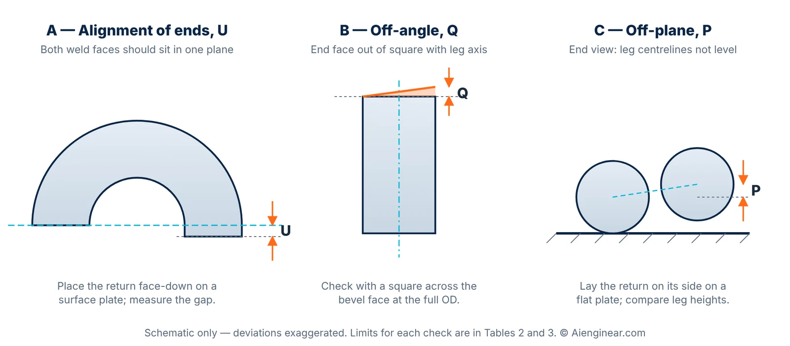
A return can be within its own tolerances and still cause fit-up trouble on a coil, because errors stack across every leg. Table 2 lists the B16.9 limits that apply to returns; Table 3 lists the angularity limits for weld-end faces.
| NPS | OD at bevel | ID at end | Wall thickness | Centre-to-centre O | Back-to-face K | Alignment of ends U |
|---|---|---|---|---|---|---|
| ½ – 2½ | +0.06 / −0.03 (+1.5 / −0.8) | 0.03 (0.8) | ≥ 87.5% of nominal | 0.25 (6.4) | 0.25 (6.4) | 0.03 (0.8) |
| 3 – 4 | 0.06 (1.5) | 0.06 (1.5) | ≥ 87.5% of nominal | 0.25 (6.4) | 0.25 (6.4) | 0.03 (0.8) |
| 5 – 8 | +0.09 / −0.06 (+2.3 / −1.5) | 0.06 (1.5) | ≥ 87.5% of nominal | 0.25 (6.4) | 0.25 (6.4) | 0.03 (0.8) |
| 10 – 18 | +0.16 / −0.12 (+4.1 / −3.0) | 0.12 (3.0) | ≥ 87.5% of nominal | 0.38 (9.7) | 0.25 (6.4) | 0.06 (1.5) |
| 20 – 24 | +0.25 / −0.19 (+6.4 / −4.8) | 0.19 (4.8) | ≥ 87.5% of nominal | 0.38 (9.7) | 0.25 (6.4) | 0.06 (1.5) |
Notes: (1) Out-of-roundness at the bevel is the sum of the absolute plus and minus OD tolerances. (2) The OD tolerance may be exceeded locally where the fitting is formed with extra thickness to meet the B16.9 design requirement. (3) The purchaser specifies the inside diameter and nominal wall at the ends; unless stated otherwise, the ID tolerance applies to OD − 2 × nominal wall. (4) Returns are only listed to NPS 24; tolerances for larger fittings are in the standard.
| NPS | Off-angle Q | Off-plane P |
|---|---|---|
| ½ – 4 | 0.03 (0.8) | 0.06 (1.5) |
| 5 – 8 | 0.06 (1.5) | 0.12 (3.0) |
| 10 – 12 | 0.09 (2.3) | 0.19 (4.8) |
| 14 – 16 | 0.09 (2.3) | 0.25 (6.4) |
| 18 – 24 | 0.12 (3.0) | 0.38 (9.7) |
Field tip: on a coil with many returns, the ±6.4 mm (0.25 in) tolerance on O can accumulate. Fit the returns to the as-built leg pitch, not the theoretical value, and tack every second leg before final welding.
Long radius or short radius: how to choose
| Factor | Long radius (1.5D) | Short radius (1.0D) |
|---|---|---|
| Space / leg pitch | Larger: O = 3 × NPS | About one-third smaller: O = 2 × NPS |
| Pressure drop | Lower (check with the pipe pressure drop calculator) | Higher; flow separates on the tight inner radius |
| Erosion / slurry / two-phase | Preferred | Avoid or upgrade wall/material |
| Pigging & cleaning | Possible with suitable pigs | Generally not piggable |
| Smallest size | NPS ½ | NPS 1 |
| Pressure design | Rated like matching pipe per B16.9 | Check carefully (see note) |
| Typical use | Default for process lines and coils | Compact coils, tight racks, low-velocity utilities |
Note: the old ASME B16.28 rated short-radius fittings at 80% of the calculated rating for straight seamless pipe of the same material and wall. When specifying SR returns today, confirm the pressure design basis in the current B16.9 text and in your piping code (for example ASME B31.3) rather than assuming SR and LR are interchangeable.
Coil layout calculator
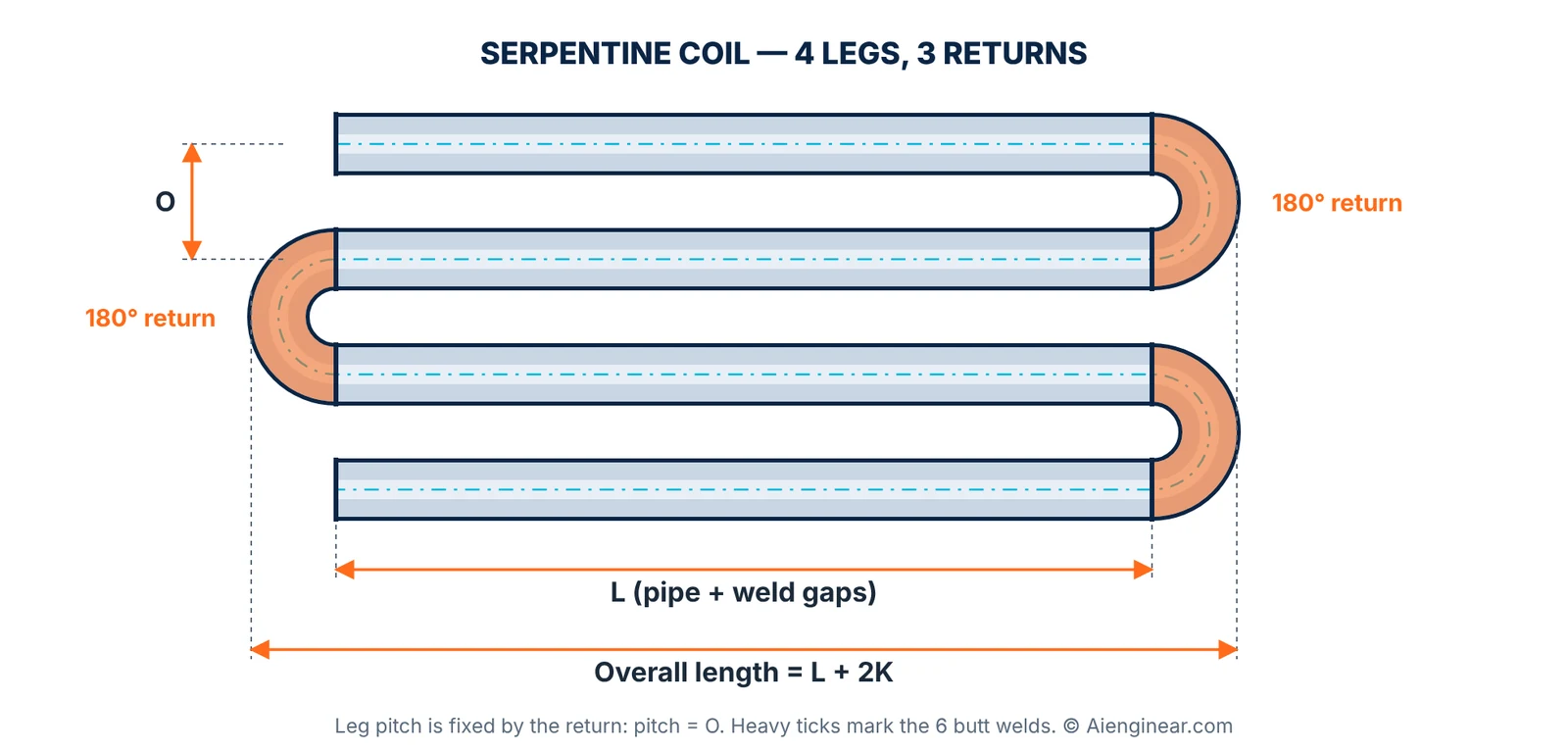
For a serpentine coil with all legs the same length and all ends aligned: leg pitch = O, overall height = (N − 1) × O + OD, and overall length = pipe length + weld gaps + 2K (only one K when there are two legs). The calculator below does this for you and counts the welds. Once the envelope is fixed, set the support spacing for the straight legs with the pipe support spacing calculator.
Serpentine coil envelope
Worked example: six legs of NPS 3 pipe, 3000 mm each, short-radius returns, 3 mm root gap. SR NPS 3 gives O = 152 mm and K = 121 mm. Overall height = 5 × 152 + 88.9 = 848.9 mm. Overall length = 3000 + 2 × 3 + 2 × 121 = 3248 mm. Five returns, ten butt welds. Switching to LR returns raises the height to 5 × 229 + 88.9 = 1233.9 mm — a 45% taller coil for the same heat-transfer length.
Weld ends, materials and marking
Weld-end preparation
B16.9 returns are supplied with buttwelding ends prepared to ASME B16.25 unless the order says otherwise. For wall thicknesses from about 3 mm to 22 mm the standard end is a single 37.5° ± 2.5° bevel with a 1.6 mm ± 0.8 mm root face; heavier walls use a compound bevel. Thin walls may be supplied square-cut. Where the return and pipe walls differ, specify the internal taper so that the transition stays within the piping code limits.
Common material specifications
| Service | Fitting specification | Typical grade | Matching pipe |
|---|---|---|---|
| Carbon steel, moderate/high temp. | ASTM A234 | WPB | A106 Gr B / A53 Gr B |
| Low-temperature carbon steel | ASTM A420 | WPL6 | A333 Gr 6 |
| Austenitic stainless | ASTM A403 | WP304/304L, WP316/316L | A312 |
| Chrome-moly | ASTM A234 | WP11, WP22, WP91 | A335 P11 / P22 / P91 |
| High-yield pipeline | MSS SP-75 / ASTM A860 | WPHY 42–70 | API 5L |
For grade selection by service and temperature, see the pipe material types and selection guide.
Related standards: light-wall stainless returns (Sch 5S and 10S) are often supplied to MSS SP-43, whose centre-to-centre and back-to-face values are substantially the same as B16.9 for NPS ½–24 but whose end tolerances differ. European EN 10253 fittings follow their own OD and radius series, so do not mix EN and B16.9 returns in one coil without checking O and K from the EN tables.
Marking
Each return should carry the manufacturer’s name or trademark, the material and product designation (for example WPB or WP316L), the schedule or nominal wall, and the size. Check the marking against the mill test certificate (EN 10204 3.1 or as specified) before the fitting goes into a spool.
Receiving inspection checklist
Use this list when returns arrive on site to confirm the return bend dimensions, tolerances and paperwork before the fittings go into spools.
- Marking matches the purchase order: size, schedule/wall, grade, heat number.
- Mill test certificate is present and the heat number on it matches the fitting. Our pipe fittings inspection guide covers the full visual, dimensional and NDT routine.
- OD at both bevels and out-of-roundness are within Table 2.
- Centre-to-centre O and back-to-face K are within ±6.4 mm (±9.7 mm on O for NPS 10–24).
- Both end faces sit flat on a surface plate within the alignment tolerance U.
- Off-angle Q and off-plane P are within Table 3.
- Wall thickness at the intrados and extrados is at least 87.5% of nominal (ultrasonic check).
- Bevel angle, root face and any internal taper match B16.25 and the weld procedure.
- No laps, cracks, arc strikes or deep grinding marks; ends protected with caps.
Key facts at a glance
Frequently asked questions
Where can I find standard return bend dimensions in mm?
Standard return bend dimensions in millimetres are listed in ASME B16.9 for long-radius returns from NPS ½ and short-radius returns from NPS 1 up to NPS 24. Table 1 on this page gives every size in mm and inches, with a one-click switch, print and CSV download.
What is the centre-to-centre dimension of a 180° return?
It is dimension O: the distance between the centrelines of the two legs. For a long-radius return it is twice the long-radius elbow centre-to-end (3 × NPS for NPS 1¼ and larger); for a short-radius return it is 2 × NPS. Example: NPS 4 LR = 305 mm, NPS 4 SR = 203 mm.
What does back-to-face (K) mean on a return bend?
K is measured from the plane of the two weld-end faces to the outside back of the bend. It tells you how far the fitting projects beyond the pipe ends and is the dimension to use for clearance, overall coil length and support location. K is roughly (O + OD) ÷ 2.
Which standard covers 180° return bend dimensions?
ASME B16.9, Factory-Made Wrought Buttwelding Fittings. The current edition is B16.9-2024. It covers both long-radius returns and short-radius 180° returns; short-radius fittings were previously published separately in ASME B16.28, which has been withdrawn.
Is ASME B16.28 still valid?
Not as a separate standard. Its short-radius elbows and returns were absorbed into ASME B16.9 and B16.28 was withdrawn. Old drawings and datasheets may still cite it; update new specifications to B16.9 unless your contract names an older edition.
What is the smallest short-radius return in ASME B16.9?
NPS 1 (DN 25), with O = 51 mm and K = 41 mm. NPS ½ and ¾ returns are listed in long radius only.
What is the difference between a long-radius and a short-radius return?
A long-radius return has a centreline radius of 1.5 × NPS; a short-radius return has 1.0 × NPS. SR saves about one-third of the leg pitch, but gives a higher pressure drop, more erosion risk at the intrados and cannot normally be pigged. LR is the default for process piping.
Can I make a return from two 90° elbows?
Yes. Two LR 90° elbows welded back-to-back give the same centre-to-centre O as an LR return, but add a girth weld, an extra NDT point and some fit-up tolerance. A one-piece return is usually cheaper and more accurate for coils.
Does the return need the same schedule as the pipe?
Order the return with the same nominal wall (schedule) and material grade as the matching pipe so that the B16.9 rating basis applies and the weld ends match. Specify any mismatched wall and the required end taper in the purchase order.
Are MSS SP-43 returns the same size as ASME B16.9 returns?
For NPS ½ to 24 the centre-to-centre O and back-to-face K of MSS SP-43 light-wall stainless returns are substantially the same as ASME B16.9. The differences are mainly in end tolerances and wall thickness (Sch 5S and 10S), so state the standard on the purchase order and check the weld-end match with the pipe.
Test your knowledge: return bend dimensions quiz
Ten quick questions on ASME B16.9 return bend dimensions, tolerances and weld ends. Pick an answer to see the explanation straight away.
Related Aienginear guides and tools
References
- ASME B16.9-2024, Factory-Made Wrought Buttwelding Fittings. The American Society of Mechanical Engineers. asme.org
- ASME B16.25, Buttwelding Ends. The American Society of Mechanical Engineers.
- ASME B31.3, Process Piping. The American Society of Mechanical Engineers.
- MSS SP-43, Wrought and Fabricated Butt-Welding Fittings for Low Pressure, Corrosion Resistant Applications. Manufacturers Standardization Society.
- ASME B16.28-1994, Wrought Steel Buttwelding Short Radius Elbows and Returns (withdrawn; content incorporated in B16.9).
- ASTM A234/A234M, A403/A403M, A420/A420M, A860/A860M — wrought fitting material specifications. ASTM International.
Disclaimer: This page is an independent engineering guide. ASME and ASTM standards are copyrighted; the values here are given for layout, estimating and checking. For fabrication, procurement and acceptance, use the edition named in your contract and the manufacturer’s certified drawings. Dimensions alone do not establish pressure rating.

Written by Muhammad Raza
Founder of Aienginear. Engineering and digital solutions professional with 26+ years managing projects, plant shutdowns and turnarounds in oil & gas, petrochemical and power generation.