
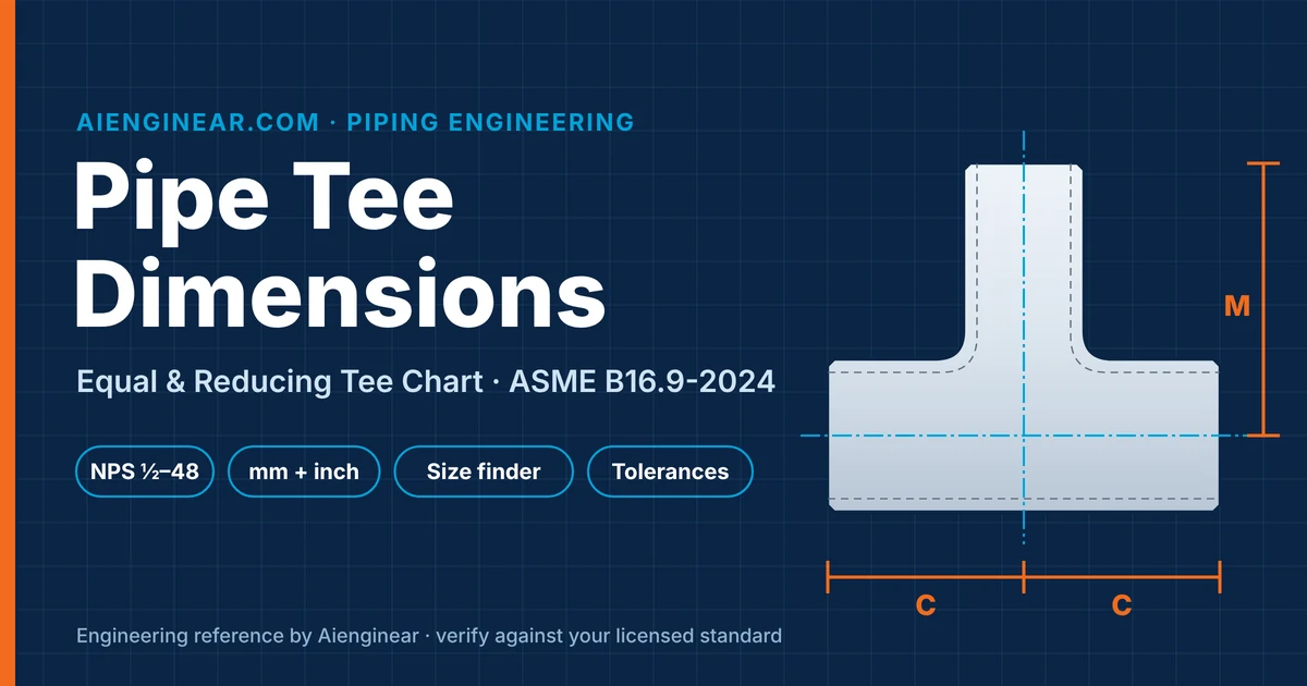
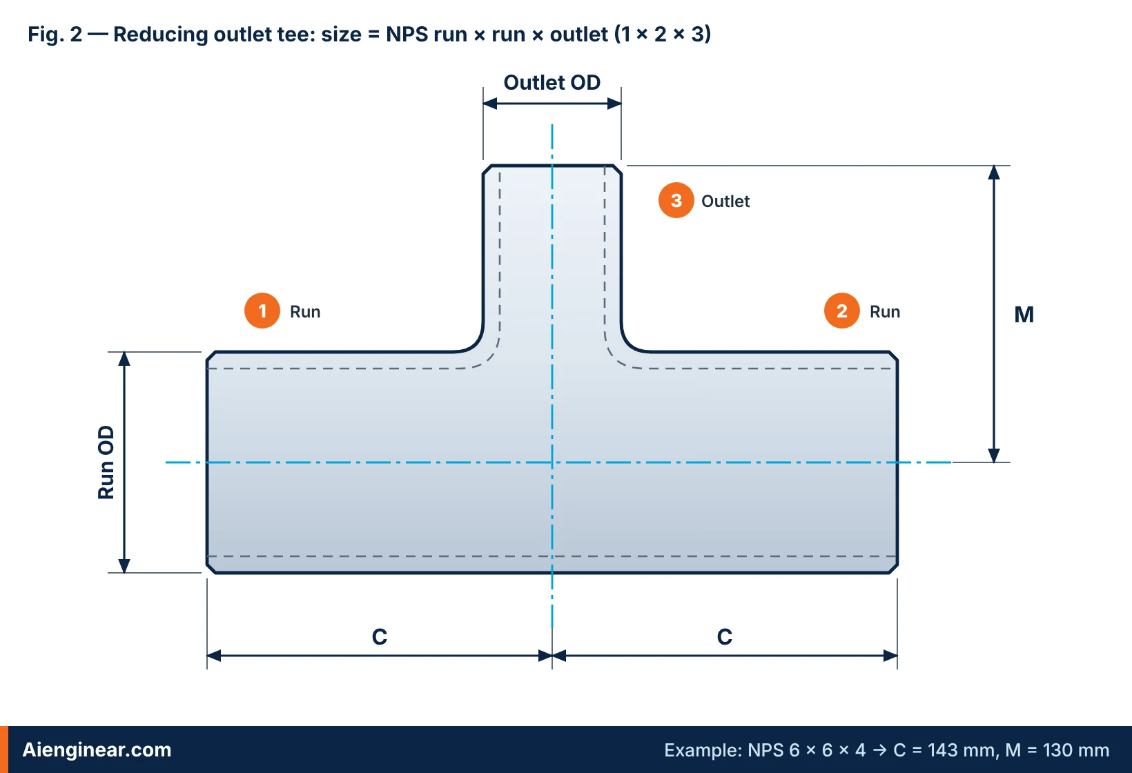
Pipe tee dimensions for butt-weld fittings are set by ASME B16.9. Each tee is defined by its run and outlet size (NPS/DN), the outside diameter at the bevel, the run center-to-end C and the outlet center-to-end M. An equal tee has the same size on all three ends (for example NPS 4: C = M = 105 mm). A reducing tee has a smaller outlet and is written run × run × outlet (for example NPS 6 × 6 × 4: C = 143 mm, M = 130 mm).
Key takeaways
- C is fixed by the run size; M depends on the outlet size. Never scale one from the other.
- Equal tees have C = M up to NPS 40; from NPS 42 to 48 the outlet M is shorter than C.
- B16.9 lists OD at bevel as 273.0 mm (NPS 10) and 323.8 mm (NPS 12) — pipe tables in ASME B36.10M show 273.1 and 323.9 for the same inch size.
- Wall thickness is not in the dimension table: you order it by schedule or nominal wall, and the ends must be at least 87.5 % of nominal.
- Overall run length of any B16.9 tee is simply 2 × C.
Tee dimension finder
Pick a run size and an outlet size to get every B16.9 dimension for that tee, the tolerance band that applies, a ready-to-paste purchase description and the pipe cut length between two fittings.
Dimensions in mm (inch in brackets). Inch values for reducing-tee M are converted from the metric column. Results are a reference aid — confirm against the licensed standard for acceptance.
What is a pipe tee?
A pipe tee is a wrought fitting with three welding ends that takes a branch off a main line at 90°. The straight-through part is the run; the side connection is the outlet or branch. Butt-weld tees are made from seamless or welded pipe, or from plate, by hot or cold forming the branch out of the parent material, then machining the ends to a weld bevel. Because the branch is formed integrally, the tee needs no separate reinforcement calculation when it is used within its rating — one of the main reasons designers choose it over a fabricated branch.
The dimensions themselves say nothing about pressure capacity. That comes from the material grade, the wall thickness ordered, the design temperature and the piping code that governs the system (ASME B31.3 for process plants, B31.1 for power piping, B31.4/B31.8 for pipelines).
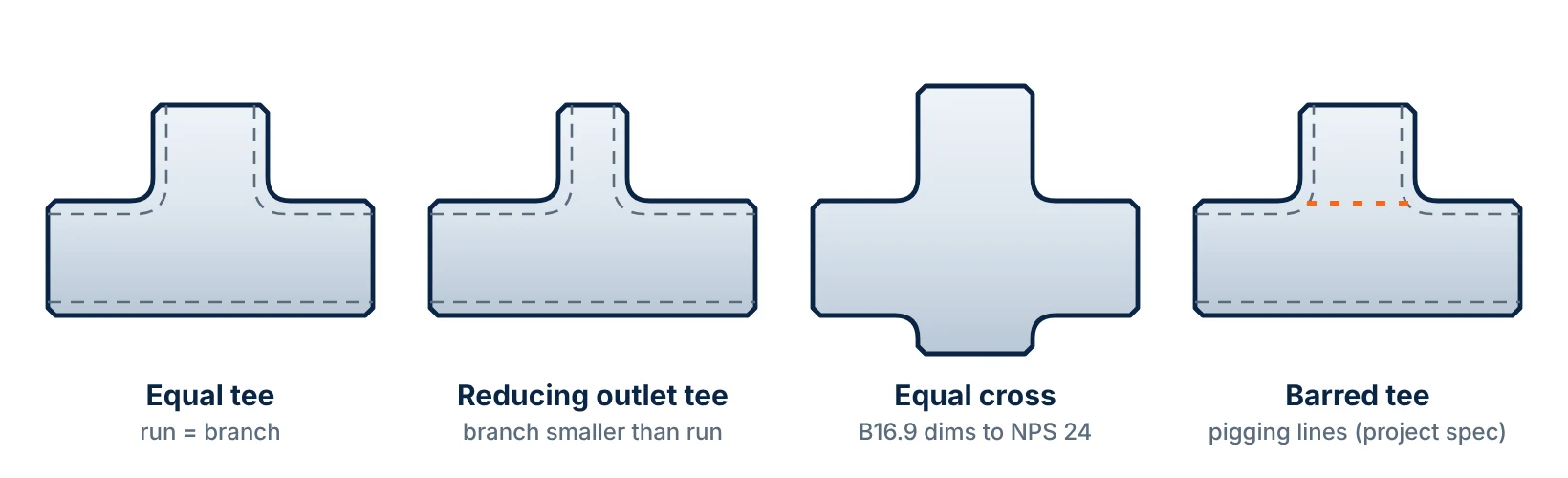
Equal (straight) tee
All three ends share one nominal size. It is the default choice for headers that split flow equally and for full-size branches such as bypasses.
Reducing outlet tee
The run is one size and the outlet is smaller. It is the usual way to take a smaller line off a header without welding a reducer onto an equal tee, saving one weld and some length. ASME B16.9 does not cover tees with a reduced run end (bullhead or run-reducing tees); those need a separate specification or a reducer.
Crosses and barred tees
A cross adds a fourth end opposite the branch; B16.9 dimensions apply to crosses up to NPS 24. A barred tee has guide bars across the branch bore so that a pig can pass along the run without entering the branch — its bar design comes from the pipeline or owner specification, while the body dimensions normally follow B16.9.
How to read tee dimensions
| Symbol | What it means | Practical note |
|---|---|---|
| NPS / DN | Nominal size of the run and outlet | A designation, not a measurement — NPS 2 pipe is 60.3 mm OD, not 50.8 mm. |
| OD | Outside diameter at the bevel of each end | Matches the mating pipe OD so the weld can be fitted without steps. |
| C | Run center-to-end: centerline intersection to the face of a run end | Same value at both run ends. Overall run length = 2C. |
| M | Outlet center-to-end: centerline intersection to the face of the branch end | Equal to C on most equal tees; smaller than C on reducing tees. |
| t | Nominal wall thickness at the ends | Specified by the purchaser (schedule or mm); minimum 87.5 % of nominal. |
| D, D1, P | Labels some catalogues use for run and outlet OD | Older charts use them; check the legend before reading values across. |
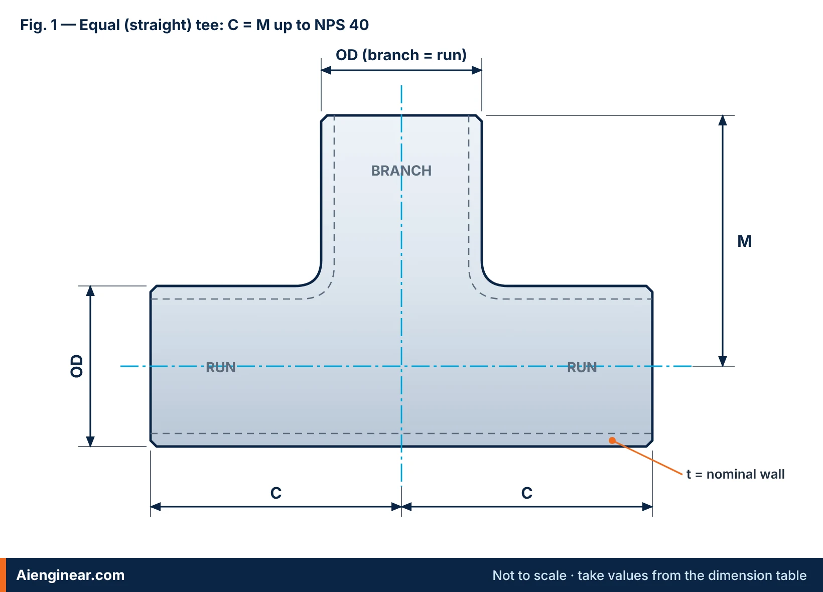
Equal tee dimensions chart — ASME B16.9 (NPS ½ to 48)
Straight-tee dimensions from the ASME B16.9 table for straight tees and crosses. Values are in millimetres; switch to inches with the toggle. Rows highlighted in orange are the large sizes where the outlet M is shorter than the run C.
Reference extract — verify against your licensed copy of ASME B16.9 and the project specification before fabrication or acceptance.
| NPS | DN | OD at bevel | C run | M outlet | Run length 2C |
|---|---|---|---|---|---|
| ½ | 15 | 21.30.84 | 251.00 | 251.00 | 502.00 |
| ¾ | 20 | 26.71.05 | 291.12 | 291.12 | 582.24 |
| 1 | 25 | 33.41.32 | 381.50 | 381.50 | 763.00 |
| 1¼ | 32 | 42.21.66 | 481.88 | 481.88 | 963.76 |
| 1½ | 40 | 48.31.90 | 572.25 | 572.25 | 1144.50 |
| 2 | 50 | 60.32.38 | 642.50 | 642.50 | 1285.00 |
| 2½ | 65 | 73.02.88 | 763.00 | 763.00 | 1526.00 |
| 3 | 80 | 88.93.50 | 863.38 | 863.38 | 1726.76 |
| 3½ | 90 | 101.64.00 | 953.75 | 953.75 | 1907.50 |
| 4 | 100 | 114.34.50 | 1054.12 | 1054.12 | 2108.24 |
| 5 | 125 | 141.35.56 | 1244.88 | 1244.88 | 2489.76 |
| 6 | 150 | 168.36.62 | 1435.62 | 1435.62 | 28611.24 |
| 8 | 200 | 219.18.62 | 1787.00 | 1787.00 | 35614.00 |
| 10 | 250 | 273.010.75 | 2168.50 | 2168.50 | 43217.00 |
| 12 | 300 | 323.812.75 | 25410.00 | 25410.00 | 50820.00 |
| 14 | 350 | 355.614.00 | 27911.00 | 27911.00 | 55822.00 |
| 16 | 400 | 406.416.00 | 30512.00 | 30512.00 | 61024.00 |
| 18 | 450 | 45718.00 | 34313.50 | 34313.50 | 68627.00 |
| 20 | 500 | 50820.00 | 38115.00 | 38115.00 | 76230.00 |
| 22 | 550 | 55922.00 | 41916.50 | 41916.50 | 83833.00 |
| 24 | 600 | 61024.00 | 43217.00 | 43217.00 | 86434.00 |
| 26 | 650 | 66026.00 | 49519.50 | 49519.50 | 99039.00 |
| 28 | 700 | 71128.00 | 52120.50 | 52120.50 | 104241.00 |
| 30 | 750 | 76230.00 | 55922.00 | 55922.00 | 111844.00 |
| 32 | 800 | 81332.00 | 59723.50 | 59723.50 | 119447.00 |
| 34 | 850 | 86434.00 | 63525.00 | 63525.00 | 127050.00 |
| 36 | 900 | 91436.00 | 67326.50 | 67326.50 | 134653.00 |
| 38 | 950 | 96538.00 | 71128.00 | 71128.00 | 142256.00 |
| 40 | 1000 | 101640.00 | 74929.50 | 74929.50 | 149859.00 |
| 42 | 1050 | 106742.00 | 76230.00 | 71128.00 | 152460.00 |
| 44 | 1100 | 111844.00 | 81332.00 | 76230.00 | 162664.00 |
| 46 | 1150 | 116846.00 | 85133.50 | 80031.50 | 170267.00 |
| 48 | 1200 | 121948.00 | 88935.00 | 83833.00 | 177870.00 |
Notes: (1) Outlet M for NPS 26 and larger is recommended, not mandatory, in B16.9. (2) Cross dimensions apply to NPS 24 and smaller. (3) Wall thickness is specified by the purchaser. (4) 2C is a derived value for layout, not a separate table entry.
Reducing tee dimensions chart — ASME B16.9 (NPS ½ to 24)
Reducing outlet tee dimensions in the three-part size form. Type a run size (for example 8 ×) or a full size (8 × 8 × 4) to filter. Run C is always the same as the equal tee of that run size; only the outlet OD and M change.
Reference extract — verify against your licensed copy of ASME B16.9 and the project specification before fabrication or acceptance.
| NPS run × run × outlet | DN | Run OD | Outlet OD | C run | M outlet |
|---|---|---|---|---|---|
| ½ × ½ × ⅜ | 15 × 15 × 10 | 21.30.84 | 17.30.68 | 251.00 | 251.00 |
| ½ × ½ × ¼ | 15 × 15 × 8 | 21.30.84 | 13.70.54 | 251.00 | 251.00 |
| ¾ × ¾ × ½ | 20 × 20 × 15 | 26.71.05 | 21.30.84 | 291.12 | 291.12 |
| ¾ × ¾ × ⅜ | 20 × 20 × 10 | 26.71.05 | 17.30.68 | 291.12 | 291.12 |
| 1 × 1 × ¾ | 25 × 25 × 20 | 33.41.32 | 26.71.05 | 381.50 | 381.50 |
| 1 × 1 × ½ | 25 × 25 × 15 | 33.41.32 | 21.30.84 | 381.50 | 381.50 |
| 1¼ × 1¼ × 1 | 32 × 32 × 25 | 42.21.66 | 33.41.32 | 481.88 | 481.88 |
| 1¼ × 1¼ × ¾ | 32 × 32 × 20 | 42.21.66 | 26.71.05 | 481.88 | 481.88 |
| 1¼ × 1¼ × ½ | 32 × 32 × 15 | 42.21.66 | 21.30.84 | 481.88 | 481.88 |
| 1½ × 1½ × 1¼ | 40 × 40 × 32 | 48.31.90 | 42.21.66 | 572.25 | 572.25 |
| 1½ × 1½ × 1 | 40 × 40 × 25 | 48.31.90 | 33.41.32 | 572.25 | 572.25 |
| 1½ × 1½ × ¾ | 40 × 40 × 20 | 48.31.90 | 26.71.05 | 572.25 | 572.25 |
| 1½ × 1½ × ½ | 40 × 40 × 15 | 48.31.90 | 21.30.84 | 572.25 | 572.25 |
| 2 × 2 × 1½ | 50 × 50 × 40 | 60.32.38 | 48.31.90 | 642.50 | 602.38 |
| 2 × 2 × 1¼ | 50 × 50 × 32 | 60.32.38 | 42.21.66 | 642.50 | 572.25 |
| 2 × 2 × 1 | 50 × 50 × 25 | 60.32.38 | 33.41.32 | 642.50 | 512.00 |
| 2 × 2 × ¾ | 50 × 50 × 20 | 60.32.38 | 26.71.05 | 642.50 | 441.75 |
| 2½ × 2½ × 2 | 65 × 65 × 50 | 73.02.88 | 60.32.38 | 763.00 | 702.75 |
| 2½ × 2½ × 1½ | 65 × 65 × 40 | 73.02.88 | 48.31.90 | 763.00 | 672.62 |
| 2½ × 2½ × 1¼ | 65 × 65 × 32 | 73.02.88 | 42.21.66 | 763.00 | 642.50 |
| 2½ × 2½ × 1 | 65 × 65 × 25 | 73.02.88 | 33.41.32 | 763.00 | 572.25 |
| 3 × 3 × 2½ | 80 × 80 × 65 | 88.93.50 | 73.02.88 | 863.38 | 833.25 |
| 3 × 3 × 2 | 80 × 80 × 50 | 88.93.50 | 60.32.38 | 863.38 | 763.00 |
| 3 × 3 × 1½ | 80 × 80 × 40 | 88.93.50 | 48.31.90 | 863.38 | 732.88 |
| 3 × 3 × 1¼ | 80 × 80 × 32 | 88.93.50 | 42.21.66 | 863.38 | 702.75 |
| 3½ × 3½ × 3 | 90 × 90 × 80 | 101.64.00 | 88.93.50 | 953.75 | 923.62 |
| 3½ × 3½ × 2½ | 90 × 90 × 65 | 101.64.00 | 73.02.88 | 953.75 | 893.50 |
| 3½ × 3½ × 2 | 90 × 90 × 50 | 101.64.00 | 60.32.38 | 953.75 | 833.25 |
| 3½ × 3½ × 1½ | 90 × 90 × 40 | 101.64.00 | 48.31.90 | 953.75 | 793.12 |
| 4 × 4 × 3½ | 100 × 100 × 90 | 114.34.50 | 101.64.00 | 1054.12 | 1024.00 |
| 4 × 4 × 3 | 100 × 100 × 80 | 114.34.50 | 88.93.50 | 1054.12 | 983.88 |
| 4 × 4 × 2½ | 100 × 100 × 65 | 114.34.50 | 73.02.88 | 1054.12 | 953.75 |
| 4 × 4 × 2 | 100 × 100 × 50 | 114.34.50 | 60.32.38 | 1054.12 | 893.50 |
| 4 × 4 × 1½ | 100 × 100 × 40 | 114.34.50 | 48.31.90 | 1054.12 | 863.38 |
| 5 × 5 × 4 | 125 × 125 × 100 | 141.35.56 | 114.34.50 | 1244.88 | 1174.62 |
| 5 × 5 × 3½ | 125 × 125 × 90 | 141.35.56 | 101.64.00 | 1244.88 | 1144.50 |
| 5 × 5 × 3 | 125 × 125 × 80 | 141.35.56 | 88.93.50 | 1244.88 | 1114.38 |
| 5 × 5 × 2½ | 125 × 125 × 65 | 141.35.56 | 73.02.88 | 1244.88 | 1084.25 |
| 5 × 5 × 2 | 125 × 125 × 50 | 141.35.56 | 60.32.38 | 1244.88 | 1054.12 |
| 6 × 6 × 5 | 150 × 150 × 125 | 168.36.62 | 141.35.56 | 1435.62 | 1375.38 |
| 6 × 6 × 4 | 150 × 150 × 100 | 168.36.62 | 114.34.50 | 1435.62 | 1305.12 |
| 6 × 6 × 3½ | 150 × 150 × 90 | 168.36.62 | 101.64.00 | 1435.62 | 1275.00 |
| 6 × 6 × 3 | 150 × 150 × 80 | 168.36.62 | 88.93.50 | 1435.62 | 1244.88 |
| 6 × 6 × 2½ | 150 × 150 × 65 | 168.36.62 | 73.02.88 | 1435.62 | 1214.75 |
| 8 × 8 × 6 | 200 × 200 × 150 | 219.18.62 | 168.36.62 | 1787.00 | 1686.62 |
| 8 × 8 × 5 | 200 × 200 × 125 | 219.18.62 | 141.35.56 | 1787.00 | 1626.38 |
| 8 × 8 × 4 | 200 × 200 × 100 | 219.18.62 | 114.34.50 | 1787.00 | 1566.12 |
| 8 × 8 × 3½ | 200 × 200 × 90 | 219.18.62 | 101.64.00 | 1787.00 | 1526.00 |
| 10 × 10 × 8 | 250 × 250 × 200 | 273.010.75 | 219.18.62 | 2168.50 | 2038.00 |
| 10 × 10 × 6 | 250 × 250 × 150 | 273.010.75 | 168.36.62 | 2168.50 | 1947.62 |
| 10 × 10 × 5 | 250 × 250 × 125 | 273.010.75 | 141.35.56 | 2168.50 | 1917.50 |
| 10 × 10 × 4 | 250 × 250 × 100 | 273.010.75 | 114.34.50 | 2168.50 | 1847.25 |
| 12 × 12 × 10 | 300 × 300 × 250 | 323.812.75 | 273.010.75 | 25410.00 | 2419.50 |
| 12 × 12 × 8 | 300 × 300 × 200 | 323.812.75 | 219.18.62 | 25410.00 | 2299.00 |
| 12 × 12 × 6 | 300 × 300 × 150 | 323.812.75 | 168.36.62 | 25410.00 | 2198.62 |
| 12 × 12 × 5 | 300 × 300 × 125 | 323.812.75 | 141.35.56 | 25410.00 | 2168.50 |
| 14 × 14 × 12 | 350 × 350 × 300 | 355.614.00 | 323.812.75 | 27911.00 | 27010.62 |
| 14 × 14 × 10 | 350 × 350 × 250 | 355.614.00 | 273.010.75 | 27911.00 | 25710.12 |
| 14 × 14 × 8 | 350 × 350 × 200 | 355.614.00 | 219.18.62 | 27911.00 | 2489.75 |
| 14 × 14 × 6 | 350 × 350 × 150 | 355.614.00 | 168.36.62 | 27911.00 | 2389.38 |
| 16 × 16 × 14 | 400 × 400 × 350 | 406.416.00 | 355.614.00 | 30512.00 | 30512.00 |
| 16 × 16 × 12 | 400 × 400 × 300 | 406.416.00 | 323.812.75 | 30512.00 | 29511.62 |
| 16 × 16 × 10 | 400 × 400 × 250 | 406.416.00 | 273.010.75 | 30512.00 | 28311.12 |
| 16 × 16 × 8 | 400 × 400 × 200 | 406.416.00 | 219.18.62 | 30512.00 | 27310.75 |
| 16 × 16 × 6 | 400 × 400 × 150 | 406.416.00 | 168.36.62 | 30512.00 | 26410.38 |
| 18 × 18 × 16 | 450 × 450 × 400 | 45718.00 | 406.416.00 | 34313.50 | 33013.00 |
| 18 × 18 × 14 | 450 × 450 × 350 | 45718.00 | 355.614.00 | 34313.50 | 33013.00 |
| 18 × 18 × 12 | 450 × 450 × 300 | 45718.00 | 323.812.75 | 34313.50 | 32112.62 |
| 18 × 18 × 10 | 450 × 450 × 250 | 45718.00 | 273.010.75 | 34313.50 | 30812.12 |
| 18 × 18 × 8 | 450 × 450 × 200 | 45718.00 | 219.18.62 | 34313.50 | 29811.75 |
| 20 × 20 × 18 | 500 × 500 × 450 | 50820.00 | 45718.00 | 38115.00 | 36814.50 |
| 20 × 20 × 16 | 500 × 500 × 400 | 50820.00 | 406.416.00 | 38115.00 | 35614.00 |
| 20 × 20 × 14 | 500 × 500 × 350 | 50820.00 | 355.614.00 | 38115.00 | 35614.00 |
| 20 × 20 × 12 | 500 × 500 × 300 | 50820.00 | 323.812.75 | 38115.00 | 34613.62 |
| 20 × 20 × 10 | 500 × 500 × 250 | 50820.00 | 273.010.75 | 38115.00 | 33313.12 |
| 20 × 20 × 8 | 500 × 500 × 200 | 50820.00 | 219.18.62 | 38115.00 | 32412.75 |
| 22 × 22 × 20 | 550 × 550 × 500 | 55922.00 | 50820.00 | 41916.50 | 40616.00 |
| 22 × 22 × 18 | 550 × 550 × 450 | 55922.00 | 45718.00 | 41916.50 | 39415.50 |
| 22 × 22 × 16 | 550 × 550 × 400 | 55922.00 | 406.416.00 | 41916.50 | 38115.00 |
| 22 × 22 × 14 | 550 × 550 × 350 | 55922.00 | 355.614.00 | 41916.50 | 38115.00 |
| 22 × 22 × 12 | 550 × 550 × 300 | 55922.00 | 323.812.75 | 41916.50 | 37114.62 |
| 22 × 22 × 10 | 550 × 550 × 250 | 55922.00 | 273.010.75 | 41916.50 | 35914.12 |
| 24 × 24 × 22 | 600 × 600 × 550 | 61024.00 | 55922.00 | 43217.00 | 43217.00 |
| 24 × 24 × 20 | 600 × 600 × 500 | 61024.00 | 50820.00 | 43217.00 | 43217.00 |
| 24 × 24 × 18 | 600 × 600 × 450 | 61024.00 | 45718.00 | 43217.00 | 41916.50 |
| 24 × 24 × 16 | 600 × 600 × 400 | 61024.00 | 406.416.00 | 43217.00 | 40616.00 |
| 24 × 24 × 14 | 600 × 600 × 350 | 61024.00 | 355.614.00 | 43217.00 | 40616.00 |
| 24 × 24 × 12 | 600 × 600 × 300 | 61024.00 | 323.812.75 | 43217.00 | 39715.62 |
| 24 × 24 × 10 | 600 × 600 × 250 | 61024.00 | 273.010.75 | 43217.00 | 38415.12 |
Notes: (1) For run sizes NPS 14 and larger, B16.9 gives M as recommended rather than mandatory. (2) Reducing outlet tees from NPS 26 × 26 × 12 up to NPS 48 × 48 × 46 are also covered by B16.9; take those values from the standard. (3) Outlet OD for NPS ⅜ is 17.3 mm in B16.9 (B36.10M pipe lists 17.1 mm).
Dimensional tolerances and inspection
B16.9 tolerances depend on the NPS band and on which dimension is being checked. The values below are the general fitting tolerances that apply to tees. They are published in inches; the mm column is a straight conversion (× 25.4) for convenience, so use the inch value when a result sits on the limit.
Reference extract — verify against your licensed copy of ASME B16.9 and the project specification before fabrication or acceptance.
| NPS | OD at bevel | ID at end | Wall thickness | C and M | Off-angle Q | Off-plane P |
|---|---|---|---|---|---|---|
| ½ – 2½ | +0.06 / −0.03+1.5 / −0.8 | ±0.03±0.8 | ≥ 87.5 % of nominal | ±0.06±1.5 | 0.030.8 | 0.061.5 |
| 3 – 3½ | ±0.06±1.5 | ±0.06±1.5 | ≥ 87.5 % of nominal | ±0.06±1.5 | 0.030.8 | 0.061.5 |
| 4 | ±0.06±1.5 | ±0.06±1.5 | ≥ 87.5 % of nominal | ±0.06±1.5 | 0.030.8 | 0.061.5 |
| 5 – 8 | +0.09 / −0.06+2.3 / −1.5 | ±0.06±1.5 | ≥ 87.5 % of nominal | ±0.06±1.5 | 0.061.5 | 0.123.0 |
| 10 – 12 | +0.16 / −0.12+4.1 / −3.0 | ±0.12±3.0 | ≥ 87.5 % of nominal | ±0.09±2.3 | 0.092.3 | 0.194.8 |
| 14 – 16 | +0.16 / −0.12+4.1 / −3.0 | ±0.12±3.0 | ≥ 87.5 % of nominal | ±0.09±2.3 | 0.092.3 | 0.256.3 |
| 18 | +0.16 / −0.12+4.1 / −3.0 | ±0.12±3.0 | ≥ 87.5 % of nominal | ±0.09±2.3 | 0.123.0 | 0.389.7 |
| 20 – 24 | +0.25 / −0.19+6.3 / −4.8 | ±0.19±4.8 | ≥ 87.5 % of nominal | ±0.09±2.3 | 0.123.0 | 0.389.7 |
| 26 – 30 | +0.25 / −0.19+6.3 / −4.8 | ±0.19±4.8 | ≥ 87.5 % of nominal | ±0.12±3.0 | 0.194.8 | 0.389.7 |
| 32 – 42 | +0.25 / −0.19+6.3 / −4.8 | ±0.19±4.8 | ≥ 87.5 % of nominal | ±0.19±4.8 | 0.194.8 | 0.5012.7 |
| 44 – 48 | +0.25 / −0.19+6.3 / −4.8 | ±0.19±4.8 | ≥ 87.5 % of nominal | ±0.19±4.8 | 0.184.6 | 0.7519.0 |
Unless shown otherwise, tolerances are plus and minus. Out-of-round at the ends is the sum of the absolute plus and minus OD values. The OD tolerance may not apply in local areas of formed fittings where extra wall is needed to meet the design. The ID and nominal wall at the ends are specified by the purchaser; unless stated otherwise the ID tolerance applies to the nominal ID (OD minus twice the nominal wall).
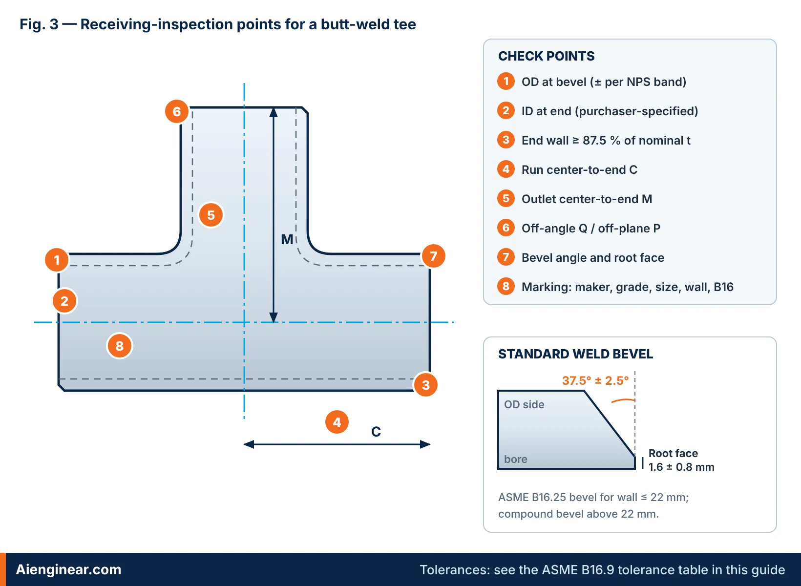
Receiving-inspection checklist
- Identity: tee type and size (run × run × outlet) match the PO and isometric.
- Marking: manufacturer, material grade, size, schedule or wall, and the B16 conformance mark are legible and match the certificate.
- Documents: heat number on the fitting traces to the mill or material test report; heat-treatment and NDE records are present where the material specification requires them.
- OD and ID at each end within the band tolerance; check two diameters 90° apart for out-of-round.
- End wall by UT gauge at four points per end — no reading below 87.5 % of nominal.
- C and M measured from a straight-edge on the centerlines, or with the tee set on a surface plate.
- Off-angle Q and off-plane P with a square across each end face.
- Bevel: to ASME B16.25 unless the PO says otherwise — 37.5° ± 2.5° with a 1.6 ± 0.8 mm root face for walls from about 5 mm up to 22 mm, a compound bevel above 22 mm; thinner walls may be square-cut or lightly chamfered.
- Surface: no cracks, laps, laminations at the bevel, deep pits or dents; protect bevels with caps until fit-up.
Wall thickness, pressure rating and materials
B16.9 does not assign pressure classes to tees the way B16.5 does to flanges. Instead, a fitting made to B16.9 is rated the same as straight seamless pipe of equivalent material and the same nominal wall. The manufacturer demonstrates this by design proof testing (a burst test) or by calculation, so the designer can treat the tee like the pipe it is ordered to match — provided the schedule and material grade are specified correctly.
That makes two purchase details critical: the wall (schedule or nominal mm at each end, which may differ between run and outlet on a reducing tee) and the material specification. Common wrought fitting specifications are:
| Service | Fitting specification | Typical grades |
|---|---|---|
| Carbon steel, ambient to elevated temperature | ASTM A234/A234M | WPB, WPC |
| Chrome-moly, high temperature | ASTM A234/A234M | WP11, WP22, WP5, WP9, WP91 |
| Low-temperature carbon steel | ASTM A420/A420M | WPL6, WPL3 |
| High-yield pipeline fittings | ASTM A860/A860M | WPHY 42 to WPHY 70 |
| Austenitic stainless steel | ASTM A403/A403M | WP304/304L, WP316/316L, WP321, WP347 |
| Duplex and super-duplex | ASTM A815/A815M | WPS31803, WPS32205, WPS32750 |
| Nickel alloys | ASTM B366/B366M | Alloy 400, 600, 625, C-276 grades |
Thin-wall stainless tees in Schedule 5S and 10S are often made to MSS SP-43. Their center-to-end values are essentially the same as B16.9 up to NPS 24, but the OD-at-bevel tolerances differ, so do not mix the two standards on one PO without saying which governs.
Using C and M in spool fabrication
On an isometric, pipe lengths are given centre-to-centre between fittings. To get the length to cut, subtract each fitting’s take-off and the root gap of every weld in that length:
Cut length = centre-to-centre distance − take-off of fitting 1 − take-off of fitting 2 − (number of welds × root gap)
For a tee, the take-off is C when the pipe leaves a run end and M when it leaves the outlet.
Two NPS 6 equal tees sit 1,500 mm apart, centre to centre, on the same header. The WPS calls for a 3 mm root gap.
Take-off of each tee (run end) = C = 143 mm. Two butt welds in the pipe length.
Cut length = 1,500 − 143 − 143 − 2 × 3 = 1,208 mm.
If the second fitting were the outlet of an NPS 8 × 8 × 6 reducing tee, its take-off would be M = 168 mm, giving 1,500 − 143 − 168 − 6 = 1,183 mm.
How to specify a tee on a purchase order
| Field | What to state | Example |
|---|---|---|
| Description | Fitting type and end connection | TEE, REDUCING, BUTT-WELD |
| Size | Run × run × outlet, NPS and/or DN | NPS 6 × 6 × 4 (DN 150 × 150 × 100) |
| Wall | Schedule or nominal mm for run and outlet ends | SCH 40 × SCH 40 |
| Dimensional standard | Edition accepted by the contract | ASME B16.9-2024 |
| Material | Specification, grade and class | ASTM A234 WPB, seamless |
| Ends | Bevel standard or special end prep | Bevelled to ASME B16.25 |
| Documents | Certificate type and records | EN 10204 3.1 MTR, dimensional report |
| Extras | Supplementary requirements | NDE, hardness limits (e.g. sour service), coating, end caps |
Tee or branch connection?
| Option | Best suited to | Watch-outs |
|---|---|---|
| Equal or reducing tee (B16.9) | Branches more than about half the run size, high-pressure or cyclic service, pigging with barred tees | Three welds; longer lead time for large or alloy sizes |
| Integrally reinforced outlet (MSS SP-97 weldolet) | Small branches off large headers | Set-on weld needs good access and NDE; check branch reinforcement limits |
| Stub-in / fabricated branch | Low-pressure utility lines | Requires a branch reinforcement calculation to the piping code (for example B31.3 para. 304.3) and often a pad |
Most project line classes include a branch table that decides this for you by run and branch size — always follow it before choosing on cost.
Common mistakes with tee dimensions
- Reading NPS as the actual outside diameter.
- Ordering a reducing tee as “6 × 4” without the repeated run size, or swapping run and outlet.
- Using C as the branch take-off on a reducing tee — it is M, and it is shorter.
- Assuming M = C for NPS 42–48 equal tees.
- Copying 273.1 / 323.9 mm pipe ODs into a fitting inspection report that should read 273.0 / 323.8 mm.
- Applying one ± value to every size instead of the tolerance for the correct NPS band.
- Treating dimensional compliance as proof that the tee is rated for the design pressure and temperature.
Frequently asked questions
What standard covers butt-weld pipe tee dimensions?
ASME B16.9, Factory-Made Wrought Buttwelding Fittings. The current edition is ASME B16.9-2024, which covers NPS ½ through NPS 48 (DN 15–1200) and sets dimensions, tolerances, ratings basis, testing and marking for straight (equal) and reducing outlet tees.
What do C and M mean on a pipe tee?
C is the run center-to-end dimension, measured from the point where the run and branch centerlines cross to the face of a run end. M is the outlet center-to-end dimension, measured from the same point to the face of the branch end.
Is M always equal to C on an equal tee?
No. On an ASME B16.9 straight tee, C and M are equal from NPS ½ to NPS 40. For NPS 42, 44, 46 and 48 the outlet dimension M is shorter than C — for example, an NPS 48 tee has C = 889 mm and M = 838 mm.
How do you write the size of a reducing tee?
Use the three-part form run × run × outlet, for example NPS 6 × 6 × 4 (DN 150 × 150 × 100). The repeated run size removes the ambiguity of the old two-part shorthand such as “6 × 4”.
What is the center-to-end dimension of a 2 inch butt-weld tee?
For an NPS 2 equal tee to ASME B16.9, C = M = 64 mm (2.50 in), and the outside diameter at the bevel is 60.3 mm (2.38 in).
What are the dimensions of a 6 × 4 reducing tee?
An NPS 6 × 6 × 4 reducing outlet tee has run OD 168.3 mm, outlet OD 114.3 mm, run center-to-end C = 143 mm and outlet center-to-end M = 130 mm.
What is the tolerance on tee center-to-end dimensions?
ASME B16.9 allows ±0.06 in (about ±1.5 mm) on C and M for NPS ½–8, ±0.09 in (±2.3 mm) for NPS 10–24, ±0.12 in (±3.0 mm) for NPS 26–30 and ±0.19 in (±4.8 mm) for NPS 32–48.
Does the tee wall thickness have to match the pipe schedule?
The tee is ordered to the schedule or nominal wall of the pipe it joins, and the wall at the welding ends must not be less than 87.5 % of that nominal thickness. Away from the ends a formed tee is often thicker, especially around the crotch, so do not assume a uniform wall.
Can I use these tee dimensions for fabrication?
Use them for layout, take-off and preliminary checks. For fabrication drawings, purchase orders and inspection acceptance, confirm every value against your licensed copy of the edition named in the contract, plus the project line class and approved drawings.
References and scope
- ASME B16.9-2024, Factory-Made Wrought Buttwelding Fittings (published 16 October 2024; supersedes the 2018 edition).
- ASME B16.25, Buttwelding Ends — weld bevel geometry.
- ASME B36.10M and B36.19M — welded/seamless and stainless pipe dimensions.
- MSS SP-43 — wrought and fabricated butt-welding fittings for low-pressure, corrosion-resistant applications.
- ASME B31.3 / B31.1 — piping design codes governing system pressure design.
- ASTM A234, A403, A420, A815, A860 and B366 — wrought fitting material specifications.

Written by Muhammad Raza
Founder of Aienginear. Engineering and digital solutions professional with 26+ years managing projects, plant shutdowns and turnarounds in oil & gas, petrochemical and power generation.