
WELDING COST · CONSUMABLES · HEAT INPUT · AWS / ASME IX / ISO · UPDATED OCTOBER 2026
Quick answer: how do you calculate welding cost?
Welding cost = labour + equipment + power + filler + flux + gas + grinding and inspection, then overhead and profit. Start from the joint: weld metal mass = cross-section area × weld length × density. Divide that mass by the deposition efficiency to get the filler to buy, and by the deposition rate to get arc time. Divide arc time by the operating (arc-on) factor to get paid welder hours, then add fit-up, set-up and interpass cleaning.
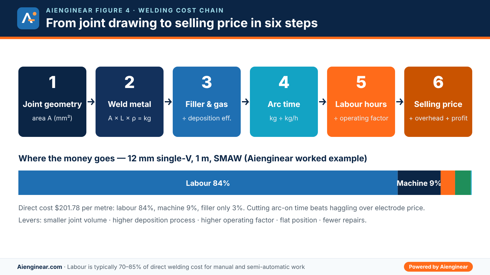
Example: 1 m of 12 mm single-V butt weld (60°) holds about 114 mm² of weld metal, or 0.90 kg. With SMAW (E7018) that needs about 1.46 kg of electrodes, 42 minutes of arc time and about 3.2 welder-hours, so labour makes up roughly 84% of direct cost. The same joint with FCAW or MCAW costs less than half as much.
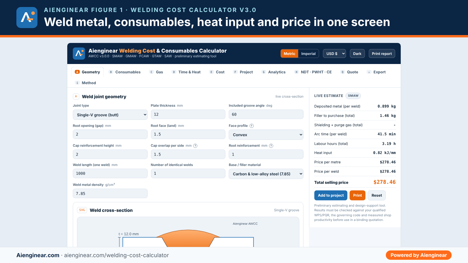
How to use the calculator
- Geometry (tab A). Pick the joint: fillet (equal or unequal legs), single-V, double-V, single-bevel, double-bevel (K), J, U, square butt or pipe butt. For pipe, choose the NPS and schedule from ASME B36.10M and the wall and OD fill in automatically. Set the face profile, cap height, cap overlap and root bead, the weld length and the number of identical welds.
- Consumables (tab B). Choose the process by ISO 4063 number (111, 135, 136, 138, 141, 121) and the filler classification. Defaults for deposition efficiency, stub loss, diameter, current and voltage load per process; replace them with your own shop data when you have it.
- Gas (tab C). Select the ISO 14175 gas group, flow rate, pre/post-flow allowance and any back-purge time. Cylinder content and price convert the volume into cylinders and money.
- Time and heat (tab D). Set deposition rate, operating factor, position (PA to PE, or 6G pipe), repair allowance and fixed times. Enter a measured travel speed and your WPS maximum heat input if you want a compliance check.
- Cost (tab E). Enter welder, helper and machine rates in your currency (USD, PKR, EUR, GBP, AED, SAR, INR and more), power tariff, overhead and profit.
- Optional tabs. Add NDT and PWHT to the estimate, screen carbon equivalent, build a multi-line weld list (tab F), compare processes (tab G), issue a quotation (tab Q), then print the branded report or export PDF, Excel, CSV, XML, SVG or a ZIP of everything.
Tip: the share link carries only the calculation inputs. Client names, price lists and revisions stay in your own browser and are never placed in the URL.
What is new in version 3.0
Version 3.0 is a full engineering review of the June 2026 tool. Several inputs in the old version were shown on screen but never used in the maths, and a few hidden assumptions changed the price without telling you. Each of those has been fixed, and the tool now carries a built-in self-test that recalculates hand-checked cases every time it loads.
Aienginear Table 1
Welding Cost Calculator v3.0 changes and corrections
Compared with v2.1 (June 2026)
| Area | v2.1 behaviour | v3.0 behaviour |
|---|---|---|
| SMAW stub and spatter loss | Inputs shown but ignored in the filler calculation | Filler = deposit ÷ [efficiency × (1 − stub loss)]; spatter folded into efficiency, with electrode count and packets |
| Flux price | Hidden at 60% of the wire price | Separate flux price input with flux-to-wire ratio and recovery |
| Fillet convexity | Cap area based on leg, not face width; equal legs only | Unequal legs, convex, flat or concave face using 2/3 × face × C, plus theoretical throat |
| Groove cap and root | Concave option subtracted metal; no cap overlap; no root bead | Convex, flat or flush cap, cap overlap past the groove edge, root bead for one-sided welds |
| Pipe weld length | Mean diameter of the wall | Centroid diameter of the actual weld area (Pappus); NPS and schedule from ASME B36.10M |
| Joint defaults | 60° on every joint, including bevels and J/U | Per-joint defaults (V 60°, bevel 45°, J 15°, U 16° included, pipe 75°) |
| Process electrical defaults | 130 A and 24 V for every process | Current, voltage, diameter, flow and k factor load per process |
| Passes | Two different pass counts (manual and automatic) | One count: automatic or manual, used for cleaning time and heat input |
| Heat input | One value with arc efficiency | Arc energy (ASME IX QW-409.1, AWS D1.1) and heat input Q = k × E (ISO/TR 17671-1), measured travel speed and WPS maximum check |
| NDT and PWHT | Calculated but never added to the price; joint rate field broken | Optional “include in estimate” with per-metre, per-joint and mobilisation rates; PWHT time per UCS-56 |
| Quantity | One weld at a time | Number of identical welds with totals, shifts and quantity-weighted project list |
| Quality checks | None | ISO 5817 levels B/C/D, ASME B31.3 reinforcement and AWS D1.1 convexity status |
| Weldability | None | CE (IIW), Pcm and CET with preheat screening notes |
| Privacy and data | Share link copied the whole state, including clients | Share link holds calculation inputs only; imported files are validated field by field |
| Branding and print | Separate sub-brand, placeholder ad and “Pro” buttons | Aienginear-branded A4 print report, currency selector, light and dark themes, keyboard-accessible tabs |
Source: Aienginear Welding Cost Calculator release notes, October 2026.
How welding cost is calculated
A defensible estimate follows one chain. Each link uses the result of the one before it, so an error in the joint area carries straight through to the price.
Filler to buy (kg) = weld metal ÷ [ηdep × (1 − stub loss)]
Arc time (h) = weld metal ÷ deposition rate (kg/h)
Labour (h) = arc time ÷ operating factor × position factor × (1 + repair) + fixed times
Gas (m³) = flow (L/min) × arc time (min) × (1 + allowance) ÷ 1000 + purge
Selling price = (labour + equipment + power + filler + flux + gas + grinding + QC + NDT + PWHT) × (1 + overhead) × (1 + profit)
The operating factor is the step most often missed. A welder paid for an eight-hour shift with SMAW rarely has the arc burning for more than two to three hours; the rest goes on changing electrodes, chipping slag, grinding, moving and fit-up. Dividing arc time by a 30% operating factor more than triples the labour hours, which is why labour, not filler, dominates the cost of manual welding.
Weld joint cross-section formulas
The cross-section area is the area of weld metal you deposit in one cut through the joint. The calculator builds it from simple shapes: the root opening (a rectangle), the bevel or radius fill (triangles and circle segments), the cap above the plate surface and, for welds made from one side, the root bead below it. Caps are treated as parabolic segments, whose area is two-thirds of width × height.
Aienginear Table 2
Weld cross-section area formulas used in the calculator
t = thickness, f = root face, h = t − f, g = root opening, α = included angle, β = bevel angle, R = root radius
| Joint | Fill area (before cap and root) | Cap width used | Typical use |
|---|---|---|---|
| Fillet, legs z₁ and z₂ | z₁·z₂/2 ± 2/3 · face · C (convex adds, concave subtracts) | face = √(z₁² + z₂²) | T, lap and corner joints |
| Square groove | g · t | g + 2 × overlap | Thin plate, up to about 3 to 6 mm by process |
| Single-V | g·t + h² · tan(α/2) | g + 2h·tan(α/2) + 2 × overlap | General butt welds, 6 to 25 mm |
| Double-V (X) | g·t + 2 (h/2)² · tan(α/2) | Each face: g + h·tan(α/2) + 2 × overlap | Thick plate welded from both sides |
| Single-bevel | g·t + h² · tan β / 2 | g + h·tan β + 2 × overlap | T-butt and corner joints, nozzle welds |
| Double-bevel (K) | g·t + 2 (h/2)² · tan β / 2 | Each face: g + (h/2)·tan β + 2 × overlap | Full-penetration T-joints in thick plate |
| Single-J | g·t + πR²/4 + R·d + d² · tan β / 2, d = h − R | g + R + d·tan β + 2 × overlap | Thick sections where one member is prepared |
| Single-U | g·t + πR²/2 + 2R·d + d² · tan(α/2), d = h − R | g + 2R + 2d·tan(α/2) + 2 × overlap | Heavy wall pipe and plate above about 25 to 30 mm |
| Pipe butt (V) | As single-V; length = π × centroid diameter | As single-V | Process and pipeline girth welds |
Source: Aienginear geometric derivation; terminology per AWS A2.4 and ISO 2553. Cap = 2/3 × cap width × height (convex) or 0.85 × width × height (flat-topped).
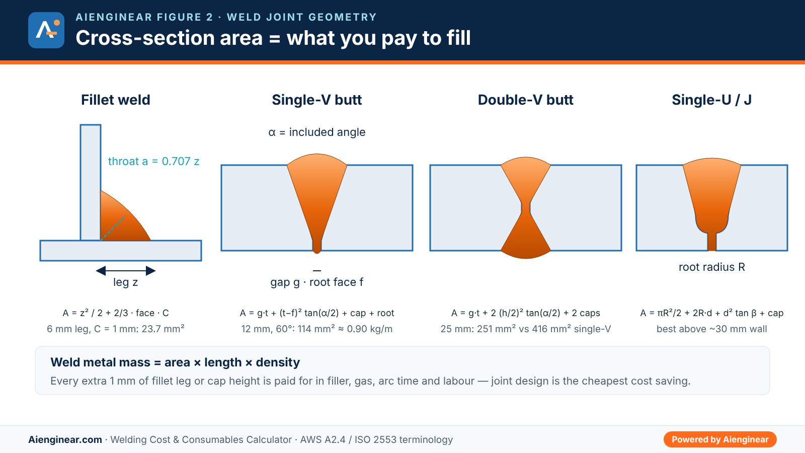
Fillet weld size and over-welding
Fillet weld metal grows with the square of the leg. Going from a 6 mm to an 8 mm fillet adds only 2 mm to the drawing but roughly 70 to 80% more weld metal, filler, gas and arc time. Oversized fillets are one of the most common hidden costs in structural and skid fabrication, so check the leg on the drawing against the design throat before quoting.
Aienginear Table 3
Fillet weld metal per metre, equal legs, carbon steel
Density 7.85 g/cm³; convexity C = 0.15 × leg, maximum 1 mm
| Leg z (mm) | Throat a (mm) | Area, flat face (mm²) | Area with convexity (mm²) | Weld metal (kg/m) | Relative to 6 mm |
|---|---|---|---|---|---|
| 3 | 2.12 | 4.5 | 5.8 | 0.045 | 0.25× |
| 4 | 2.83 | 8.0 | 10.3 | 0.081 | 0.45× |
| 5 | 3.54 | 12.5 | 16.0 | 0.126 | 0.70× |
| 6 | 4.24 | 18.0 | 23.1 | 0.181 | 1.00× |
| 8 | 5.66 | 32.0 | 39.5 | 0.310 | 1.71× |
| 10 | 7.07 | 50.0 | 59.4 | 0.467 | 2.57× |
| 12 | 8.49 | 72.0 | 83.3 | 0.654 | 3.61× |
Source: Aienginear calculator v3.0. Throat a = 0.707 z for equal legs. Double the values for fillets on both sides of a joint.
Groove weld metal by plate thickness
On butt welds, the choice of preparation matters more as the plate gets thicker. A single-V grows with the square of the thickness, while a double-V splits the depth in two and a U groove keeps the sides nearly parallel. Above roughly 20 mm, a double-V cuts weld metal by about 35 to 45%, provided you can turn the work or weld from both sides.
Aienginear Table 4
Butt weld cross-section and weld metal per metre by thickness
V: 60° included, 2 mm gap · double-V: 2 mm face · U: 16° included, R 6 mm, no gap · 2 mm convex cap, 1.5 mm overlap
| Thickness (mm) | Single-V (mm²) | Double-V (mm²) | Single-U (mm²) | Single-V (kg/m) | Double-V (kg/m) |
|---|---|---|---|---|---|
| 6 | 41 | 36 | 50 | 0.32 | 0.28 |
| 10 | 85 | 64 | 111 | 0.67 | 0.50 |
| 12 | 114 | 82 | 138 | 0.90 | 0.64 |
| 16 | 186 | 123 | 195 | 1.46 | 0.97 |
| 20 | 277 | 175 | 256 | 2.17 | 1.37 |
| 25 | 416 | 251 | 339 | 3.26 | 1.97 |
| 32 | 659 | 383 | 467 | 5.17 | 3.01 |
| 40 | 1006 | 569 | 630 | 7.89 | 4.46 |
Source: Aienginear calculator v3.0, carbon steel 7.85 g/cm³. Single-V and single-U include a 1 mm root bead; double-V includes a cap on both faces.
Deposition efficiency, rate and operating factor
Three numbers describe a process for estimating. Deposition efficiency is the share of melted filler that ends up in the joint after spatter, slag and coating losses. Deposition rate is the weld metal laid down per arc-on hour. Operating factor is the share of paid time with the arc burning. For stick electrodes the unused stub is a separate loss: a 50 mm stub on a 350 mm electrode is about 14% of what you bought.
Aienginear Table 5
Process screening data for welding cost estimates
Calculator defaults; replace with measured shop values when available
| Process (ISO 4063) | Deposition efficiency | Overall filler yield | Typical deposition rate | Operating factor | Default set-up | k (ISO/TR 17671-1) |
|---|---|---|---|---|---|---|
| SMAW / MMA (111) | 65–75% | 55–65% incl. stub | 1–2 kg/h | 20–35% | 3.2 mm, 125 A, 23 V | 0.8 |
| GMAW / MAG solid wire (135) | 90–95% | 90–95% | 2.5–5 kg/h | 35–50% | 1.2 mm, 250 A, 27 V | 0.8 |
| FCAW flux-cored (136) | 80–88% | 80–88% | 3–6 kg/h | 35–50% | 1.2 mm, 230 A, 26 V | 0.8 |
| MCAW metal-cored (138) | 92–97% | 92–97% | 3.5–7 kg/h | 35–50% | 1.2 mm, 270 A, 28 V | 0.8 |
| GTAW / TIG (141) | 95–100% | 95–100% | 0.3–1 kg/h | 20–35% | 2.4 mm rod, 140 A, 12 V | 0.6 |
| SAW submerged arc (121) | 98–100% (wire) | 98–100% + flux | 6–15 kg/h single wire | 50–90% | 4.0 mm, 600 A, 32 V | 1.0 |
| Orbital GTAW (mechanised) | 95–100% | 95–100% | 0.4–1 kg/h | 40–60% | 0.9 mm wire, 120 A, 11 V | 0.6 |
Source: Aienginear estimating defaults compiled from typical manufacturer data; k factors per ISO/TR 17671-1. Values vary with diameter, current, position and operator.
Shielding gas consumption
Gas use is flow rate × arc time, plus an allowance for pre-flow, post-flow, purging the hose and small leaks. Ten percent is a reasonable starting allowance; poor practice can double it. For stainless steel, duplex and nickel alloy pipe, the root needs a back-purge as well, which the calculator tracks as a separate flow and time so that the shielding and purge volumes are not mixed up.
Aienginear Table 6
Shielding gases, typical flow rates and cylinder content
Classification per ISO 14175; volumes at about 1 atm and 15 °C
| ISO 14175 group | Composition | Typical use | Typical flow (L/min) | Typical cylinder content |
|---|---|---|---|---|
| C1 | 100% CO₂ | MAG and FCAW on carbon steel, deep penetration, more spatter | 15–20 | 30 kg liquid ≈ 15 m³ |
| M21 | Ar + 15–25% CO₂ | General MAG, FCAW and MCAW on carbon steel | 14–20 | 50 L at 200 bar ≈ 9.5–10 m³ |
| M20 | Ar + 5–15% CO₂ | Spray and pulsed MAG, thinner material | 14–18 | 50 L at 200 bar ≈ 9.5–10 m³ |
| M13 | Ar + 1–3% O₂ | MIG on stainless steel | 14–18 | 50 L at 200 bar ≈ 9.5–10 m³ |
| I1 | 100% Ar | TIG on all metals, MIG on aluminium, back-purge | 8–12 (TIG) | 50 L at 200 bar ≈ 9.5–10 m³ |
| I3 | Ar + He | Thick aluminium and copper, faster TIG | 12–20 | about 9 m³ |
Source: Aienginear calculator v3.0 defaults; check flow rates against your WPS and the supplier’s cylinder data.
Arc energy and heat input
Codes use two related quantities, and mixing them up is a common source of non-conformances on impact-tested procedures. ASME Section IX QW-409.1 and AWS D1.1 work with arc energy, the electrical energy per unit length with no efficiency factor. European practice (EN ISO 15614-1 with ISO/TR 17671-1, formerly EN 1011-1) uses heat input, which multiplies arc energy by a thermal efficiency factor k for the process.
Heat input Q (kJ/mm) = k × E k = 1.0 SAW · 0.8 SMAW, GMAW, FCAW, MCAW · 0.6 GTAW
Travel speed estimate (mm/min) = deposition rate ÷ (density × bead area per pass)
Aienginear Table 7
Arc energy and heat input by code
Which value to compare with your WPS limit
| Code / document | Quantity | Formula | Notes |
|---|---|---|---|
| ASME BPVC Section IX, QW-409.1(a) | Heat input (arc energy) | V × A × 60 ÷ travel speed | No efficiency factor; applies when impact testing is a supplementary essential variable |
| ASME IX QW-409.1(c) | Instantaneous energy or power | Energy (J) or power (W) from the machine display ÷ length | Required for waveform-controlled (pulsed, synergic) welding |
| AWS D1.1 | Heat input | V × A × 60 ÷ travel speed | Used in WPS qualification and the annex on preheat methods |
| EN ISO 15614-1 with ISO/TR 17671-1 | Heat input Q | k × U × I ÷ v × 10⁻³ | k by process; the calculator shows both E and Q |
Source: Aienginear summary of ASME BPVC Section IX, AWS D1.1/D1.1M and ISO/TR 17671-1. Always check the edition your contract invokes.
Worked example: 12 mm single-V butt weld, 1 m, SMAW
Inputs: carbon steel plate 12 mm thick, 60° included angle, 2 mm root opening, 1.5 mm root face, 2 mm convex cap with 1.5 mm overlap each side, 1 mm root bead, flat position. E7018 electrodes 3.2 mm at 125 A and 23 V, deposition efficiency 70%, stub loss 12%, deposition rate 1.3 kg/h, operating factor 30%, repair allowance 5%. Rates: welder 35, helper 18, machine 6 per hour, power 0.15 per kWh, filler 4.00 per kg with 10% markup, grinding 4 and QC 3 per weld, overhead 20%, profit 15%.
Aienginear Table 8
Worked example: 12 mm single-V, 1 m, SMAW E7018
Step-by-step results, matching the calculator defaults
| Step | Calculation | Result |
|---|---|---|
| 1. Cross-section | Gap 2 × 12 = 24.00; bevels 10.5² × tan 30° = 63.65; cap 2/3 × 17.12 × 2 = 22.83; root 2/3 × 6 × 1 = 4.00 | 114.5 mm² |
| 2. Weld metal | 114.5 mm² × 1000 mm × 7.85 g/cm³ | 0.899 kg |
| 3. Electrodes to buy | 0.899 ÷ (0.70 × 0.88) | 1.46 kg (about 43 electrodes) |
| 4. Arc time | 0.899 kg ÷ 1.3 kg/h | 41.5 min |
| 5. Passes | 114.5 mm² ÷ about 18 mm² per SMAW pass | 7 passes |
| 6. Labour | 0.691 h ÷ 0.30 × 1.0 × 1.05 = 2.42 h, plus fit-up 15 + set-up 10 + cleaning 7 × 3 = 46 min | 3.19 h |
| 7. Heat input | Travel 169 mm/min (estimated); E = 23 × 125 × 60 ÷ (1000 × 169); Q = 0.8 × E | E 1.02, Q 0.82 kJ/mm |
| 8. Direct cost | Labour 168.87 + machine 19.12 + power 0.37 + filler 6.42 + grinding 4.00 + QC 3.00 | 201.78 |
| 9. Selling price | 201.78 + overhead 40.36 + profit 36.32 | 278.46 per metre |
| 10. Distortion screen | Transverse shrinkage 0.2 × 114.5 ÷ 12 + 0.05 × 2 | about 2.0 mm |
Source: Aienginear calculator v3.0 self-checked result. Currency-neutral: use your own rates.
The lesson from step 8 is clear: electrodes cost 6.42 of a 201.78 direct cost. Even a 20% discount on filler saves less than 1%, while raising the operating factor from 30% to 40% saves about 20% of the labour.
Process comparison
The Analytics tab reruns the same joint with each process, loading that process’s own efficiency, deposition rate, operating factor, current and voltage. The cost gap comes almost entirely from arc time and operating factor.
Aienginear Table 9
Same joint, six processes: 12 mm single-V, 1 m
Calculator defaults, flat position, same rates and margins as the worked example
| Process | Filler to buy (kg) | Arc time (min) | Labour (h) | Gas (m³) | Heat input Q (kJ/mm) | Selling price |
|---|---|---|---|---|---|---|
| SMAW (111) | 1.46 | 41.5 | 3.19 | 0 | 0.82 | 278.46 |
| GMAW (135) | 0.97 | 15.9 | 1.36 | 0.26 | 1.03 | 131.53 |
| FCAW (136) | 1.06 | 13.5 | 1.21 | 0.27 | 0.97 | 119.52 |
| MCAW (138) | 0.95 | 12.0 | 1.14 | 0.24 | 1.09 | 113.01 |
| GTAW (141) | 0.93 | 107.8 | 8.57 | 1.19 | 0.54 | 735.11 |
| SAW (121) | 0.91 + flux | 6.3 | 0.77 | 0 | 2.44 | 80.75 |
Source: Aienginear calculator v3.0. SAW heat input is far higher; check it against impact-tested WPS limits before switching.
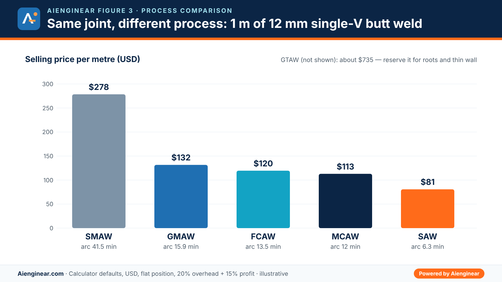
A common practical split on pipe and pressure work is a GTAW root and hot pass for quality, followed by SMAW, FCAW or SAW fill and cap for speed. Price each stage as a separate line in the Project tab to see the blended cost.
NDT, PWHT and preheat costs
Inspection and heat treatment can rival the welding itself on pressure work. In v3.0 they are priced in tab H and only added to the estimate when you tick “Include in estimate”, so a structural job is not loaded with costs it will never carry.
- NDT: price by metre examined, by joint, or both, with a mobilisation lump sum. ASME B31.3 normal fluid service needs at least 5% random radiography or ultrasonic examination of circumferential butt welds; ASME VIII ties spot or full radiography to the joint efficiency you design with; AWS D1.1 follows the contract documents.
- PWHT: holding time and controlled heating and cooling are computed from ASME VIII Division 1 UCS-56 for P-No.1 steel; add uncontrolled time and the furnace or local heating rate.
- Preheat: the CE (IIW), Pcm and CET values show whether preheat is likely. The minimum preheat itself must come from your WPS or code table, then enter the preheat minutes per weld in tab D.
Aienginear Table 10
PWHT holding time and rate limits, P-No.1 carbon steel
ASME VIII Division 1 UCS-56 rules as applied in the calculator; holding at 595 °C minimum
| Governing thickness (mm) | Minimum holding time | Max heating rate above 425 °C | Max cooling rate above 425 °C |
|---|---|---|---|
| 6 | 15 min | 222 °C/h | 278 °C/h |
| 12 | 29 min | 222 °C/h | 278 °C/h |
| 25 | 60 min | 222 °C/h | 278 °C/h |
| 50 | 120 min | 111 °C/h | 139 °C/h |
| 75 | 135 min | 74 °C/h | 93 °C/h |
| 100 | 150 min | 56 °C/h | 70 °C/h |
Source: Aienginear summary of ASME BPVC Section VIII Division 1 UCS-56 (1 h per 25 mm up to 50 mm, 15 min minimum; 2 h plus 15 min per additional 25 mm above 50 mm; rates 5550/t and 6950/t °C/h, not below 55 °C/h). ASME B31.3 Table 331.1.1 and EN 13445-4 differ; use your governing code.
Weld profile limits that drive cost
Excess cap height and convexity are paid for twice: once to deposit the metal and again to grind it off if the inspector rejects it. The calculator flags the cap you entered against these limits on the Geometry tab.
Aienginear Table 11
Reinforcement and convexity limits used for the profile checks
b = cap or face width, t = thinner member thickness
| Standard | Feature | Limit |
|---|---|---|
| ISO 5817 level B (stringent) | Butt weld excess weld metal / fillet excess convexity | h ≤ 1 mm + 0.1 b, max 5 mm / max 3 mm |
| ISO 5817 level C (intermediate) | Butt weld excess weld metal / fillet excess convexity | h ≤ 1 mm + 0.15 b, max 7 mm / max 4 mm |
| ISO 5817 level D (moderate) | Butt weld excess weld metal / fillet excess convexity | h ≤ 1 mm + 0.25 b, max 10 mm / max 5 mm |
| ASME B31.3 Table 341.3.2 | Girth weld reinforcement, normal fluid service | t ≤ 6 mm: 1.5 mm · 6–13 mm: 3 mm · 13–25 mm: 4 mm · over 25 mm: 5 mm |
| AWS D1.1 | Fillet weld convexity | Face width ≤ 8 mm: 1.6 mm · 8–25 mm: 3 mm · 25 mm and over: 5 mm |
Source: Aienginear summary of ISO 5817, ASME B31.3 and AWS D1.1/D1.1M. Severe cyclic, category M and high-pressure services are stricter; confirm against the edition in your contract.
How to reduce welding cost
- Weld to size, not over size. Specify the fillet leg the design needs and control convexity; every extra millimetre is squared.
- Choose the leanest preparation. Double-V or double-bevel on thick plate, U grooves on heavy wall, and a smaller included angle where the process allows access.
- Move to a higher-deposition process for fill passes. FCAW, MCAW or SAW where position, wind and the WPS allow.
- Raise the operating factor. Better fit-up, positioners, pre-cut consumables, wire feeders on long leads and fewer trips to the store keep the arc burning.
- Weld flat wherever possible. Rolling pipe or turning assemblies to PA/1G can save a third of the time of vertical or overhead work.
- Cut repairs. A repair costs several times the original weld once gouging, re-welding, re-inspection and schedule delay are counted.
Common estimating mistakes
Aienginear Table 12
Welding estimating mistakes, consequences and fixes
Seen repeatedly in fabrication and site tenders
| Mistake | Consequence | How the calculator handles it |
|---|---|---|
| Treating arc time as paid time | Labour under-priced by a factor of 3 to 5 for manual welding | Divides arc time by the operating factor every time |
| Ignoring the cap, root bead and root opening | Groove weld metal under-estimated by 20 to 40% | Adds gap, cap with overlap and root bead |
| Buying electrodes equal to the deposit | Stick electrodes run short by 35 to 45% | Applies deposition efficiency and stub loss, gives a piece count |
| One flat rate for every position | Vertical, overhead and 6G pipe welds lose money | Position factor from PA to PE and 6G |
| Forgetting flux, purge gas and pre/post-flow | Consumables under-priced on SAW and stainless pipe | Separate flux, purge and gas allowance inputs |
| Quoting heat input without the code’s definition | WPS limits breached on impact-tested work | Shows arc energy (ASME IX) and heat input with k (ISO) |
| Leaving out NDT, PWHT and repairs | Margin wiped out on pressure work | Optional NDT and PWHT lines, repair allowance |
Source: Aienginear project experience, power, oil and gas and cement plant fabrication.
How this calculator compares
Aienginear Table 13
Aienginear Welding Cost Calculator v3.0 vs typical online welding calculators
Feature check, October 2026
| Feature | Aienginear v3.0 | Typical free calculator |
|---|---|---|
| Joint types | 9, incl. unequal fillet, J, U, K and pipe by NPS/schedule | Fillet and V only |
| Cap, overlap and root bead | Yes, with ISO 5817, B31.3 and AWS checks | Rarely |
| Processes | SMAW, GMAW, FCAW, MCAW, GTAW, SAW, orbital | 2 to 3 |
| Electrode count, spools, flux, purge gas | Yes | Filler mass only |
| Arc energy and heat input by code | ASME IX and ISO/TR 17671-1, with WPS check | Single value or none |
| NDT, PWHT (UCS-56), CE / Pcm / CET | Yes | No |
| Multi-weld project list and quotation | Yes, with revisions and clients | No |
| Exports | Branded print, PDF, XLSX, CSV, XML, SVG, ZIP | Screen only |
| Units and currency | Metric / imperial, 10 currencies | Usually one |
| Privacy | Runs in the browser, no sign-up, nothing uploaded | Often requires an account |
Source: Aienginear feature review of commonly used free welding calculators, October 2026.
Assumptions and limitations. This is a preliminary estimating and design-support tool. Joint areas are geometric idealisations; real fit-up gaps, mismatch and bead shape vary. Deposition rates, efficiencies and operating factors are typical values and must be replaced with measured shop or site data for binding quotes. Heat input, preheat and PWHT outputs are screening aids and do not replace the qualified WPS/PQR or the governing code. Distortion figures are indicative only.
Standards and references
Aienginear Table 14
Standards behind the calculator
Check the edition named in your contract or code of construction
| Standard | Used for |
|---|---|
| AWS A2.4 / ISO 2553 | Joint, groove and weld symbol terminology |
| AWS D1.1/D1.1M | Structural steel welding, fillet profile limits, heat input |
| ASME BPVC Section IX | QW-409.1 heat input and waveform-controlled welding, WPS/PQR |
| ASME B31.3 | Reinforcement limits (Table 341.3.2), examination extent, PWHT |
| ASME BPVC Section VIII Div.1 | UCS-56 PWHT holding time and heating/cooling rates |
| ASME B36.10M | Pipe outside diameter and wall thickness by NPS and schedule |
| API 1104 | Pipeline girth welding reference for the WPS sheet |
| ISO 5817 | Quality levels B, C and D for imperfections |
| ISO/TR 17671-1 (formerly EN 1011-1) | Heat input and thermal efficiency factor k |
| EN 1011-2 | CET carbon equivalent and preheat methods for ferritic steels |
| EN ISO 15614-1 | Welding procedure qualification |
| ISO 4063 / ISO 6947 / ISO 14175 | Process numbers, welding positions and shielding gas groups |
Source: Aienginear standards register, October 2026. Standards are referenced, not reproduced.
Quick quiz: test your welding cost knowledge
Related Aienginear calculators and guides
Frequently asked questions
How do you calculate welding cost per metre?
Find the joint cross-section area, multiply by one metre and the metal density to get the weld metal mass, then convert it into filler (divide by deposition efficiency), arc time (divide by deposition rate) and paid labour (divide by operating factor and add fixed times). Price labour, equipment, power, filler, gas, grinding and inspection, add overhead and profit, and divide by the total weld length.
How many electrodes are needed per metre of weld?
Divide the weld metal mass by the overall electrode yield, typically 55 to 65% for SMAW once stub loss is included, then multiply by the electrodes per kilogram for the size. A 12 mm single-V butt weld holds about 0.90 kg per metre, so it needs about 1.46 kg of E7018, or roughly 43 electrodes of 3.2 × 350 mm.
What is deposition efficiency in welding?
Deposition efficiency is the share of the filler melted that ends up as weld metal. Typical values are 65 to 75% for stick electrodes before stub loss, 90 to 95% for solid wire, 80 to 88% for flux-cored wire, 92 to 97% for metal-cored wire and close to 100% for TIG rod and submerged-arc wire.
How do you calculate shielding gas consumption?
Multiply the flow rate by the arc time and add an allowance for pre-flow, post-flow and leaks, usually about 10%. For example, 15 L/min for 16 minutes of arc time with a 10% allowance is about 264 litres, or 0.26 m³. Add back-purge gas separately for stainless and alloy pipe roots.
How is weld heat input calculated?
Arc energy in kJ/mm is voltage × current × 60 divided by 1000 × travel speed in mm/min, which is the value used by ASME Section IX QW-409.1 and AWS D1.1. ISO/TR 17671-1 multiplies arc energy by a thermal efficiency factor k: 1.0 for SAW, 0.8 for SMAW, GMAW and FCAW, and 0.6 for GTAW. At 23 V, 125 A and 169 mm/min, arc energy is 1.02 kJ/mm and heat input is 0.82 kJ/mm.
What is the operating factor in welding?
The operating factor, also called the arc-on time or duty cycle, is the percentage of a welder’s paid time with the arc actually burning. It is typically 20 to 35% for stick welding, 35 to 50% for semi-automatic wire welding and 50 to 90% for mechanised submerged-arc welding. It is the biggest single driver of welding labour cost.
Which welding process is cheapest?
For the same joint, high-deposition processes with high operating factors cost least: SAW, then metal-cored and flux-cored wire, then solid wire GMAW, with SMAW and GTAW the most expensive per metre. The final choice must also satisfy material, position, access, site wind conditions, heat input limits and the qualified WPS.
How much does a fillet weld weigh per metre?
An equal-leg fillet weighs about leg² ÷ 2 × 7.85 ÷ 1000 kg per metre in steel before convexity. With typical convexity, a 6 mm fillet is about 0.18 kg/m, an 8 mm fillet about 0.31 kg/m and a 10 mm fillet about 0.47 kg/m.
Can this calculator be used for a binding quotation?
It gives a structured preliminary estimate that follows accepted fabrication practice. Before a binding quotation, replace the default deposition rates, efficiencies and operating factors with your own measured data, confirm the joint details against the drawing and WPS, and include site-specific items such as access, scaffolding, weather protection and testing.
Key takeaways
- Weld metal = area × length × density; every cost in the estimate follows from it.
- Labour is usually 70 to 85% of direct welding cost, so arc-on time matters more than filler price.
- Fillet weld metal rises with the square of the leg; over-welding is an expensive habit.
- Double-V or U preparations save 35 to 45% of weld metal on thick sections.
- Report arc energy for ASME IX and AWS D1.1, and heat input with k for ISO-based procedures.
- Price NDT, PWHT and repairs explicitly on pressure work.

Written by Muhammad Raza
Founder of Aienginear. Engineering and digital solutions professional with 26+ years managing projects, plant shutdowns and turnarounds in oil & gas, petrochemical and power generation.